Friday, September 26, 2014

The Long Road To The Rhosydd Rubbish Tip

This is the fourth post on building a Rhosydd quarry rubbish wagon since I started back in June, but as you can see I've now completed the model. If you remember the first step was to design the 3D printed underframe and figure out how to build the top half from sheet brass. The second step was adding all those rivets before a quick third post with the metal top posed on a 3 bar slab wagon to give a rough idea of the final model. The final piece of the puzzle was actually printing the underframe.

This is the first model I've designed in which I've combined a 3D printed part with parts from another material and I'm really happy with how it's turned out. I could have tried to 3D print the whole model but the upper body would have been way too chunky; I used 0.12mm brass but the thinnest I could have printed the parts would have been 0.3mm and I'd probably have had to have the side walls at 0.6mm as they would have been unsupported during printing.

The use of two materials did leave me wondering if it was worth making the model available to others or not though; painting a 3D printed model is much easier than fabricating half the model from a flat sheet of brass. In the end I've decided that the top is easy enough to make (see my nice detailed instructions) that most people should be able to make up the part without any issues. I've made up quite a few of them now to check the instructions and to find the best order of the folds etc. that I'm fairly certain that anyone with a sharp pair of scissors a modelling knife and something to help make the folds could make the part almost without thinking. So if you fancy a go (just to prove me wrong) then I'll happily sell you an underframe or three.

Tuesday, September 23, 2014

Up To Scratch?

Having finished the basic structure of my first scratchbuilt building in the previous post, I got on with doing the roof and painting it. For some reason it didn't seem worth doing separate posts for each stage so I'll just take you through the whole process in a single post. Anyway, lets start at the end with a shot of the completed building (remember the gap under the door is so I can sink the building).


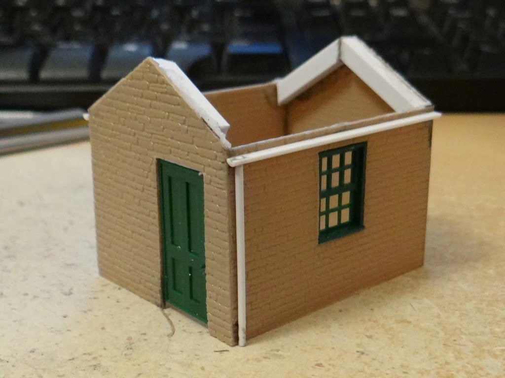
Hopefully you'll all agree that this looks a lot better than it did in the previous post! So how did I turn the rather tatty looking shell of a building into something that while not perfect I'm still fairly proud of? Well it all started with a triangular needle file.


One of my main concerns, which I didn't mention at the time, was that at the corners the brick courses didn't match up very well, especially where you could see the edge of the plastikard sheet. I'd tried to fix this using a scalpel to cut the courses into place without much success. Fortunately Martin picked up on the corners in a comment and pointed me in the direction of a triangular file. Quite why I'd not thought of this myself I don't know, but just two minutes with a file and the building looked a lot better.

Once I'd sorted the corner joints the next job was the roof. I started by fixing a piece of cardboard in place to form the base of the roof before I moved onto figuring out how to add the tiles. My approach to covering the roof in slates was to follow the ideas described by David Wright in his book Making Rural Buildings for Model Railways. Unfortunately I made a couple of mistakes which would come back to bite me later. Essentially the approach involves drawing out slates in strips onto card and then cutting part way into each strip. This means you can lay an entire row of slates in one go as the join between them is hidden by the next row placed on top. I decided to use Princess Slates which are apparently 24 inches by 14 inches in size. Now I don't know how much overlap there usually is between two rows of slates but the book suggests a third. Unfortunately I misread this as a half so the rows are closer together than they should be. I also made the mistake of using normal copier paper for the slates. The problem with this became obvious as soon as I sprayed on some primer. Essentially because I'd applied the tiles as strips and the thinness of the paper the gaps between adjacent slates kind of disappeared. I carried on with painting but we will return to the slates later.

Basic painting followed a fairly simple pattern; a base colour followed by some dry brushing and a black wash. The roof used dark sea grey (Model Color #991) followed by a black wash and then dry brushing first with a little Dark Blue Grey (Model Color #904) and then black. The walls were painted first with Weathered Stone (RailMatch #2426) before a black wash and then dry brushing with khaki, brown sand, dark sand (Model Color #988, #876, and #847), and black. At this point you can see the problem with the roof tiles quite clearly, but I carried on regardless.


With the basic painting done I turned to the details, specifically the door and window frame. I was originally going to go for a dirty white for the window but Bryony suggested a worn and faded blue paint used everywhere might look better. The base coat was a 4 to 1 mixture of Flat Blue and Dark Blue Grey (Model Color #962 and #904) with then a light dry brushing of more Dark Blue Grey before a black wash to really make things look dirty. I think this has worked really well, although in retrospect the window sill maybe should have been modelled as stone rather than painted wood. Having essentially finished the building at this point I came to the conclusion that I really wasn't happy with the roof.

Unfortunately because I'd built the model as a single piece it wasn't possible to remove the existing roof, certainly not without damaging the painting I'd already done. So instead I simply laid another layer of slates over the top. This time I made them from 220gms card and ehile they are much better they still aren't perfect. Next time I might do separate slates instead of fitting a row in a single go.

The problem with the extra layer of slates was that the roof was now quite proud of the side walls. To hide this I decided to add barge boards which I cobbled together from some 0.5mm plastruct strip. I used a file to roughen the surface slightly to try and imitate wood grain although I'm not sure how successful that was. They were then painted in the same way as the door and window frame before being super-glued into place. Annoyingly after fitting them I realised they were possibly a bit short; the cowboy builders have struck again! At this point I also added a sill above the door from a short piece of right-angle plastruct which I think adds a nice little touch to the door and helps to hide the edge of the plastikard sheet.

Now usually I leave glazing windows until the very end as I want the "glass" to be nice and shiny. In this case I wanted the windows to end up looking as if they hadn't been cleaned in years, so I used Micro Kristal Klear to add the individual panes before I wafted over a light layer of matt varnish to seal everything in place. Looking at the final model I decided that the guttering was too pristine so toned this down by dry brushing a little London Grey (Model Color #836) over the metalwork and then a second coat of matt varnish made sure the windows were nice and frosted and the paint well sealed.

As I said at the start of this post the building is far from perfect but I'm really happy with how it has turned out and the amount of things I've learnt along the way. The next building is bound to be much better given my experiences here. This building was never destined for my layout so I think I'll build it a little diorama as an excuse for more scenic experimentation rather than simply throwing it away.

Wednesday, September 17, 2014

Cowboy Builders

As a slight change from building locomotives and rolling stock I decided that I'd have a go at turning some of the 4mm scale Slater's embossed Plastikard that I bought back in July into a small building to see how well it worked and how exactly to use it. My original plan had been to build a cardboard shell and then to cover it in the plastikard as this would make a nice rigid structure. Unfortunately I suffered a severe cause of cowboy builder.

I spent quite a while drawing out the parts on the computer and made templates for the four walls in 2mm cardboard and then four walls in the plastikard to match. Unfortunately I managed to get the sizing wrong when going from the shell to the outer layer. Having cut out all 8 parts it was clear that they wouldn't go together, but it was also clear that the 2mm cardboard was too think for the wall depth I wanted, given the door and window parts I had to hand (these are from the PECO building components pack, part number LK-78). Rather than trying to redraw the cardboard shell I decided, given it was only a small test building, to just use the plastikard without any reinforcement. So I set about joining the walls together using plastic weld from E.M.A. Model Supplies.

I'm still amazed at just how strong a joint the plastic weld creates, and once all four walls were joined the structure is remarkably solid. While the window frame fitted nicely I decided I needed a little more depth to the door. This was easy to achieve by simply adding some 0.5mm plastruct strip around the door frame using more plastic weld (note to self: make sure the window is open wider next time you use this stuff). There is a gap under the door as I'm intending the bottom few millimeters of wall to be underground so the building won't appear to float.

The rest of the bits you can see are all more sections of plastruct. There are some 4mm square sections used as roof girders to thicken the side walls and give me somewhere to attach the roof. The gutter is 2mm half round and the drain pipe is 1.3mm rod; I drilled a hole in the half round and slotted the rod in to make a nice solid joint.

The next step is to sort the roof. I'm going to experiment with adding separate roof tiles so it might take a while, even though it is only a small roof. Once that's done it will be on to painting, which will hopefully hide some of the more cowboy builder aspects. For a first attempt it's ... well if I'm being honest fairly terrible. Terrible it may be but at least I'm learning things that will be useful for the next attempt.

Tuesday, September 16, 2014

Canopus: Covering Up The Solder

While I was fairly happy with my soldering of the chassis I do think hiding most of it behind a layer of paint improves things no end! This is by no means the final layer of paint the chassis will see, but I decided to get a base coat on (it's Humbrol matt black primer) and to paint in the flycranks before going any further. The next step is to permanently affix the coupling rods at which point it would be difficult to paint the chassis, and almost impossible to neatly paint the flycranks.

There are still a few parts that need to be glued or soldered to the chassis, which I can't fit yet, so I will have to remove small areas of paint to get a good joint, but it should be easy to touch up the paintwork, and anyway most of the chassis is hidden or will be shadowed by the body.

The good news is that having stripped it down, painted it, and then reassembled it, it still runs nice and smoothly.

Monday, September 15, 2014

Changing Points ... With Style

Back in May I started looking into how I would operate the points on the OO9 gauge layout I'm intending to build. I made the decision to use a servo to throw each point and wrote two posts, one on the electronics and one on actually using the setup to throw an OO9 point. The one thing missing in both of those posts was an actual switch of any kind; I triggered the point throw by simply pulling one of the Arduino pins to ground with a short piece of wire which is clearly not a long term solution. The second of my railway related birthday presents (the first being the Heath Robinson book) has solved the problem in a very stylish fashion.

The solution to the problem is a Cobalt-S switch lever from DCCconcepts. Essentially this is a simple combination of a momentary switch and two SPDT switches, but it is packaged to look and work like an old fashioned point/signal lever. Of the nine wires I've currently just used two (one half of one SPDT) to trigger the electronics.


The angle of the video doesn't really show off the lever at its best although it does nicely show the lock mechanism. I've also yet to paint it or attach the rest of the detailing parts, but I think we can all agree that it's quite a stylish way to change the points. I'll need to pick up another one at some point as I'm planning two points on the layout but that is one more decision taken.

Friday, September 12, 2014

Three Bars or Four?

You may remember that back in June I designed and 3D printed some small 3 bar slab wagons. These were reasonably well received albeit with some helpful suggestions. When I ordered the Aberllefenni box wagons I also updated the 3 bar slab wagon and printed another set as well as a 4 bar variant. I got side tracked by building Canopus though and so have only just got around to assembling and painting these.

It's difficult to tell from a photo but I do think the 3 bar version looks much better now that I've extended the bars slightly; it really is a very small change but it gives a much better balanced model. The 4 bar variant is of a similar size although it includes some extra details taken from a number of prototype photos etc, again these are kind of difficult to see in the photo. As usual, both are now available via Penistone Railway Works (3 bar, 4 bar) should you fancy a few.

Monday, September 8, 2014

Canopus: It's Alive!

Okay, so while I know that my plan was to paint the chassis next (before it would be difficult to get at with all the motion permanently attached) I just couldn't stop myself from performing a quick in-situ test of the gearbox and motor.


Given that this is the first locomotive I've built where I've had to form the entire chassis and gearbox I'm really happy to see all the wheels turning move under their own power. The test did highlight a slight issue with the way I'd put the gearbox together though.

When I was working out which way around to fit the gearwheel to the gearbox I worked from the idea that I should align the larger part of the gear with the shaft of the motor to ensure it meshed well with the worm gear. Unfortunately because of the way around I'd fitted the axles this didn't work, but I only found out once I'd fitted everything together properly.

If you look at the gear on the rear axle you will notice that on the lower surface it has a boss that extends out along the axle which isn't present on the top surface (you can just about see this in the photo to the left, but it is a lot clearer in the photos from the previous post. The problem is that when the gearbox is fitted the larger part of the gearwheel is fouled by the boss if it is fitted on that side of the axle gear.

Fortunately it is easy to fix this by simple rotating the gear in the gearbox (given I can't swap the wheels around as they are permanently trapped in the chassis). Although the worm and gear are now no longer in line they still mesh nicely and everything turns freely.

Saturday, September 6, 2014

Canopus: Building the Gearbox

As I mentioned in a previous post, I was a little concerned about building the gearbox for Canopus as the supplied parts differed from those originally used in the kit and it appeared that the new parts wouldn't build into a working gearbox. Fortunately I have now built a working gearbox, but before we get to that let me show you the problem with following the instructions given the change of parts.


As you can see from the first photo the gearbox fits between the rear driving wheels. The instructions say to solder the bearings to the outside of the gearbox and then file off anything that protrudes through to the inside. This is easy to do, but when you then fold the gearbox to shape you find that the clearance between the bearings on the outside of the gearbox and the wheels is very minimal. I couldn't actually see a gap although the wheels did turn freely without moving the gearbox. With such minimal clearance though any slight movement and chances are the wheels would touch the gearbox and this would likely lead to a short as the chassis is live. I'm assuming that this wasn't a problem with the kit originally but results from a change to the actual gears. Originally two separate gears were supplied rather than the new combined gear and I'm guessing that they fitted onto a thinner shaft and that the appropriate bearings had a smaller outer face.

The change in gears presents a second more important problem. The width of the two original gears appears to have been equal to the inner dimensions of the gearbox. With an interference fit between the gears and the shaft this would mean that they wouldn't move sideways within the gearbox. Unfortunately the new gear is much thinner. This means that the shaft is free to move sideways and any sideways movement causes it to drop out of one of the bearings. It would also appear that the shaft is a little undersized as the gear is a very loose fit; it measures 1.97mm and is loose in the bearings designed for a 2mm axle (they are the same as those used for the wheels). Fortunately it turns out that both problems are solvable without too much effort.


As you can see from the photo I've assembled the gearbox while completely ignoring the instructions. Firstly I've fitted the two bearings from the inside instead of the outside of the gearbox to improve the clearance with the backs of the wheels. Secondly I've replaced the shaft with some 2mm brass rod (yes I know I need to cut it to match the width of the gearbox but I've left it long so you can see it) as this is ever so slightly thicker (0.03mm to be precise) than the original and is a tight interference fit with the gear wheel. While the gear no longer slides on the shaft it would still move sideways in the bearings but I've solved this using a third bearing. The kit contained a spare 2mm bearing which just happens to be the perfect width to fill the gap. So now I have a gear box where there is no sideways movement, the gear wheel is a tight fit to the shaft, and the shaft rotates freely. A quick test with a 9V battery and the motor shows that it works perfectly; I haven't fully pushed the worm gear onto the motor shaft as once it is on it will be difficult to get off and it can only be fitted once the motor and gearbox are fitted to the chassis.

So I know have a working gearbox, I just need to trim down the brass rod before fitting it to the chassis. I'm thinking that the next step might be to paint the chassis because once the motor is fitted it can't easily be removed and I don't want to risk getting paint in the wrong place. Also it will be easier to paint the cranks etc. before permanently fixing the coupling rods and adding the rest of the motion.

Monday, September 1, 2014

Heath Robinson

Now before anyone gets any ideas, Heath Robinson is not a description of my attempt at building the gearbox for Canopus. I've actually not done any more work on Canopus since the previous post as we've been away on holiday.

Even though I don't have any modelling updates to report, I thought a post was in order, and fortunately one of my recent birthday presents gives me something to blog about. I actually got two railway related presents, but you'll have to wait a bit for details on the second one. Today I give you a very brief review of Railway Ribaldry by W. Heath Robinson.

This clearly isn't a new book, the author died in 1944, but is a new reprint of a book originally published in 1935 to commemorate the centenary of the Great Western Railway. As you would expect, the book is a series of cartoons or illustrations showing weird and wacky railway inventions. It's not a long book, there are about 100 drawings, but it is certainly amusing and this nice quality reprint (it's not a cheap paperback just put out to make money) does the original justice.