So I think I've now got the 16mm scale chassis from I P Engineering back to where it was before it suffered from rust. As well as painting it (to stop the rust reoccuring) I've also made some modifications and while I could write about them I thought I'd try something new and have shot a short video where I talk through the changes I've made.
I don't really like the sound of my voice when I hear it back, so I don't think this will become a frequent occurance, but it would be great to know what people think about the video and if they think I should do more posts like this.
Showing posts with label video. Show all posts
Showing posts with label video. Show all posts
Saturday, November 26, 2022

Thursday, June 16, 2022
Two Wheels, One Axle
Having messed up the first attempt at axle making I spent some actual time thinking through the process a bit and came up with a plan. This essentially involved keeping a long piece of 1/8" axle steel nice and straight on the lathe using a fixed steady (a recent purcahse and this is the first time I've tried it) and then lightly makring the sections for an axle on the rod using the cutting tool. I could then cut the axle from the rod and face and turn with just the end protruding from the collet chuck. Unfortunately I forgot to take any photos while marking up the axles, but here you can see the end result (after I roughly cut the two sections from the rod).
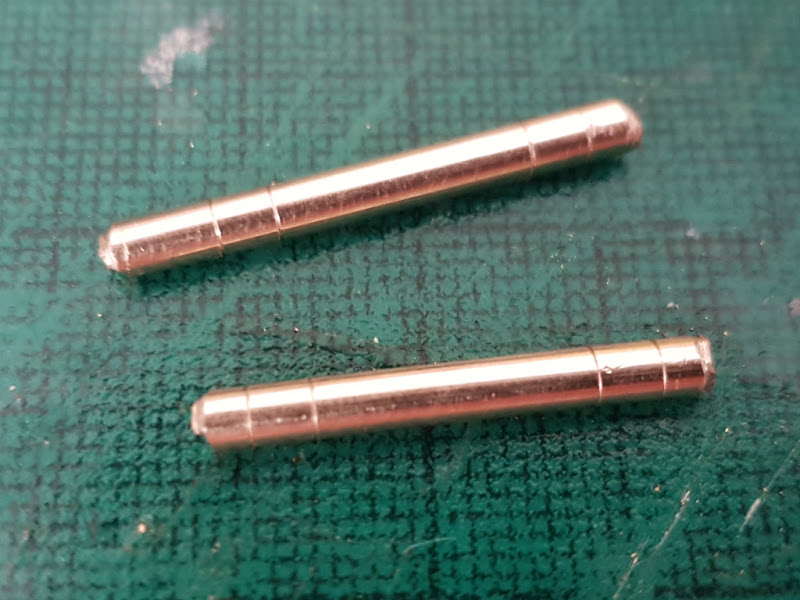 So if you look at those you can see I roughly cut them from the rod, so from each end I need to face off at the first line, and then turn down the rod between the first and second line. This will give me a stepped axle which should enforce the correct back-to-back measurement; although each end needs turning down differently to match the insulated and uninsulated wheels.
So far I've only managed to do one axle but......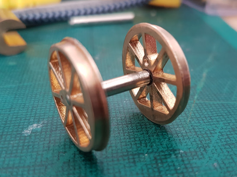 And just to prove that they both fit on track and roll
And you have no idea just how happy I am with that!

So far I've only managed to do one axle but......

And you have no idea just how happy I am with that!
Friday, July 6, 2018
Powered Waggly Bits
So having fixed the cylinders to Canopus it was clear that the clearances were minimal behind the crossheads. Slowly turning the motor over by hand and everything seemed okay, although on one side it did look as if the crosshead was pushing on the retaining nut on the front flycrank. Under power everything did move but it was very jerky as the two parts rubbed against each other.
On closer inspection it turns out that when I widened the slidebars I didn't refit them completely central, so while one side was very tight for clearances there was quite a lot of space on the other side. So I've now removed the cylinders and slidebars, refitted the slidebars more centrally and then refitted the cylinders. Although the clearances are still tight I can now see daylight between the parts all through a full rotation of the wheels. More importantly under power it seems to run quite nicely.
Next up is the pony truck, which unsurprisingly will need modifying before it can be fitted, but more on that next time.
On closer inspection it turns out that when I widened the slidebars I didn't refit them completely central, so while one side was very tight for clearances there was quite a lot of space on the other side. So I've now removed the cylinders and slidebars, refitted the slidebars more centrally and then refitted the cylinders. Although the clearances are still tight I can now see daylight between the parts all through a full rotation of the wheels. More importantly under power it seems to run quite nicely.
Next up is the pony truck, which unsurprisingly will need modifying before it can be fitted, but more on that next time.
Thursday, June 21, 2018
Clayton #5843 in Ex-Works Conditon
It's been three years since I first started work on a model of Clayton #5843, and in that time I've worked on three different models. The first had issues around the print bending and was never finished. The second was built for running on Rhyd but balance issues meant the heavy pewter driver figure caused the loco to kangaroo along the track, so he had to be replaced by a plastic figure. I've now finally finished the third iteration of the model (another commission so I've still not built one for myself) that includes more weight and finally allows the nice pewter figure from Andrew C Stadden to take it's place in the "cab".
It's new owner has requested it in ex-works condition (so they can have it weathered to match existing stock) and so here it is fresh from the paint shop.


While it would benefit from a little more running in (difficult on my short O14 test track) it's running a lot smoother than previous versions with the driver figure on board and is showing no sign of bouncing along the track.
Now I really should get another set of parts together and build one for myself, but first I'll need to take a trip to the post office to get this one on the way to its new home.
It's new owner has requested it in ex-works condition (so they can have it weathered to match existing stock) and so here it is fresh from the paint shop.


While it would benefit from a little more running in (difficult on my short O14 test track) it's running a lot smoother than previous versions with the driver figure on board and is showing no sign of bouncing along the track.
Now I really should get another set of parts together and build one for myself, but first I'll need to take a trip to the post office to get this one on the way to its new home.
Thursday, January 26, 2017
21 Pages
Some of you may remember that way back in July of 2015 I started work on a small diorama depicting a disused railway bridge. I built the model as an entry into that years Dave Brewer Memorial Challenge held at ExponNG at the end of October.

Over the roughly three months I spent working on the model I learnt an awful lot of useful and interesting techniques, and while I'd documented them on the blog I thought that, even though I'd not won the challenge, an article on the building of the model might be interesting to a wider audience than this blog enjoys.
Having written for Narrow Gauge & Industrial Railway Modelling REVIEW before I ran the idea past the editor, Roy C. Link, who agreed it was an interesting topic for an article. My original plan was to put an article together fairly quickly by pulling text and images from some of the blog posts I'd already written. Clearly things didn't quite go to plan as it took a year before the article was finished, but it finally appeared in the most recent issue (109) of the REVIEW.
 It wasn't that I was particularly slow in writing the article, in fact as I hoped it would it started to come together quite quickly from the posts I'd already made. What happened was that I decided to include a little more of the history of the bridge and the railway it was part of in the article and once I started to do some research things kind of snowballed.
What I discovered was that the line over Duchal Moor was one of only two railways in Scotland, the other being at Dalmunzie, that had been built to aid access to grouse shooting moors. So my research expanded from a derelict bride to two entire railways and as such took a lot longer than planned. It also resulted in more details emerging than would sensibly fit in an article that was predominately about a small diorama so it became two articles; one on the modelling of the bridge and one entirely devoted to the history of the two lines.
Given that both lines were closed or abandoned over thirty years ago and neither were ever open to the general public tracking down enough information to produce an interesting article took some time. I was very fortunate that requests for information in a couple of places turned up people who had either visited one or other of the lines, or had useful photos and documents which they were willing to share. The result was a 12 page article including a detailed history of the lines and rolling stock, maps, and a number of previously unpublished photos. Of course these 12 pages are in addition to the 9 page article on the bridge model, hence the title of this post as issue 109 of the REVIEW contains 21 pages of my work. Viewed another way, assuming my maths is right, about 45% of the magazine is stuff I put together, so hopefully people will enjoy both articles; it's worth buying for the other 55% alone!
If you are interested in reading the articles then you'll have to pick up a copy of the REVIEW as I can't simply repost all the material here (you should be able to get issue 109 as a back issue shortly) but I do have one thing to share with you all.
When researching the line at Dalmunzie I came across an old cine film which had already been digitized and uploaded to YouTube. The entire film is made up of a number of reels shot over a number of years and shows life on the Dalmunzie estate. While the whole film is interesting if you are only interested in the railway then there are three clips at 8:30, 29:50, and 30:40.

Over the roughly three months I spent working on the model I learnt an awful lot of useful and interesting techniques, and while I'd documented them on the blog I thought that, even though I'd not won the challenge, an article on the building of the model might be interesting to a wider audience than this blog enjoys.
Having written for Narrow Gauge & Industrial Railway Modelling REVIEW before I ran the idea past the editor, Roy C. Link, who agreed it was an interesting topic for an article. My original plan was to put an article together fairly quickly by pulling text and images from some of the blog posts I'd already written. Clearly things didn't quite go to plan as it took a year before the article was finished, but it finally appeared in the most recent issue (109) of the REVIEW.

What I discovered was that the line over Duchal Moor was one of only two railways in Scotland, the other being at Dalmunzie, that had been built to aid access to grouse shooting moors. So my research expanded from a derelict bride to two entire railways and as such took a lot longer than planned. It also resulted in more details emerging than would sensibly fit in an article that was predominately about a small diorama so it became two articles; one on the modelling of the bridge and one entirely devoted to the history of the two lines.
Given that both lines were closed or abandoned over thirty years ago and neither were ever open to the general public tracking down enough information to produce an interesting article took some time. I was very fortunate that requests for information in a couple of places turned up people who had either visited one or other of the lines, or had useful photos and documents which they were willing to share. The result was a 12 page article including a detailed history of the lines and rolling stock, maps, and a number of previously unpublished photos. Of course these 12 pages are in addition to the 9 page article on the bridge model, hence the title of this post as issue 109 of the REVIEW contains 21 pages of my work. Viewed another way, assuming my maths is right, about 45% of the magazine is stuff I put together, so hopefully people will enjoy both articles; it's worth buying for the other 55% alone!
If you are interested in reading the articles then you'll have to pick up a copy of the REVIEW as I can't simply repost all the material here (you should be able to get issue 109 as a back issue shortly) but I do have one thing to share with you all.
When researching the line at Dalmunzie I came across an old cine film which had already been digitized and uploaded to YouTube. The entire film is made up of a number of reels shot over a number of years and shows life on the Dalmunzie estate. While the whole film is interesting if you are only interested in the railway then there are three clips at 8:30, 29:50, and 30:40.
Saturday, December 5, 2015
Turn to the Right
Having now recieved my order for more rail I've continued on with my O14 point building experiment. The first attempt was for a very tight Type 1 point which in retrospect was going to be a struggle even for short wheelbase locos so for my second attempt I've switched to the slightly less severe Type 2 point. Of course with more rail to hand I've gone a lot further than just building the central frog section, in fact I've built an entire point.


I've deviated from the suggested instructions in quite a few places though as I've built the point onto copperclad sleepers rather than the suggested plastic sleepers. This meant that I had to gap the rails to ensure that the polarity of the frog could switch when the points changed. I also simplified the tiebar slightly by not trying to fit nice looking plates and rivets but using a bit of wire instead. Of course photos on their own don't show you if any of this was successful or not so here is a video of me testing it.
So yes it does work, but I'm not entirely happy with it. Mostly I'm not happy with the hinges. Drilling the holes to make the two parts of the rail line up properly was a real pain. So having recently seen someone else build one without hinges where they relied on the rail flexing instead I'm going to have another go and see if that is a better approach. Still not bad for a first attempt.


I've deviated from the suggested instructions in quite a few places though as I've built the point onto copperclad sleepers rather than the suggested plastic sleepers. This meant that I had to gap the rails to ensure that the polarity of the frog could switch when the points changed. I also simplified the tiebar slightly by not trying to fit nice looking plates and rivets but using a bit of wire instead. Of course photos on their own don't show you if any of this was successful or not so here is a video of me testing it.
So yes it does work, but I'm not entirely happy with it. Mostly I'm not happy with the hinges. Drilling the holes to make the two parts of the rail line up properly was a real pain. So having recently seen someone else build one without hinges where they relied on the rail flexing instead I'm going to have another go and see if that is a better approach. Still not bad for a first attempt.
Monday, November 2, 2015
Down at the Bottom of the Garden
So less than an hour after getting home from ExpoNG yesterday (there will be a post on that later) I was stood at the bottom of the garden camera in hand waiting to watch a train go by. Of course I wasn't interested in the local service train but the second running this year of the Tin Bath. Since February we've done enough work in the garden that I could actually get to the bottom fence and one of the fence posts made an excellent tripod.
Tuesday, August 18, 2015
Clayton: Completed Build #1
Other than adding the makers plates I've finished the first build of the Clayton loco I've been working on. As I mentioned before there are more things wrong with the current version than right but it's still assembled into a passable model.


I've rally enjoyed modelling on O14 as the larger scale has really let me go to town on the details. Not only do we have the brake lever from a previous post, but individual wires and a bell among other details that would have been difficult or impossible in OO9. Now a static model is one thing but you all probably want to see it move.
You'll probably notice two things from that video. Firstly the working lights are missing as I discovered that there was no way of routing the wires through the current print (another thing to add to the list of bits needing a redesign). Secondly the movement isn't very smooth. For some reason it looks as if they wheels are sticking during part of their revolution. It must be the wheels and not the layshaft as it's at the same point every time. You can see it more clearly in this video.
I've not figured out exactly what the problem is yet but I'm guessing that maybe one of the axles is slightly out of line leading to a tight spot. I'll try and investigate further but it may just be an issue with printing that will go away after some of the bits are redesigned anyway.
So not perfect, but I'm more than happy with my start in O14.


I've rally enjoyed modelling on O14 as the larger scale has really let me go to town on the details. Not only do we have the brake lever from a previous post, but individual wires and a bell among other details that would have been difficult or impossible in OO9. Now a static model is one thing but you all probably want to see it move.
You'll probably notice two things from that video. Firstly the working lights are missing as I discovered that there was no way of routing the wires through the current print (another thing to add to the list of bits needing a redesign). Secondly the movement isn't very smooth. For some reason it looks as if they wheels are sticking during part of their revolution. It must be the wheels and not the layshaft as it's at the same point every time. You can see it more clearly in this video.
I've not figured out exactly what the problem is yet but I'm guessing that maybe one of the axles is slightly out of line leading to a tight spot. I'll try and investigate further but it may just be an issue with printing that will go away after some of the bits are redesigned anyway.
So not perfect, but I'm more than happy with my start in O14.
Sunday, May 17, 2015
Lazy Sunday Afternoon
Since the weekend I visited Rainford when I messed up the pickups on the Hudson-Hunslet there hasn't been much time for doing any modelling. Today though I set myself the challenge of fixing the pickups once and for all.
My hunch was that the 0.112mm phosphor bronze wire I had was perfect as it was springy enough while having a tiny surface area so as not to introduce lots of extra friction. What I realised this morning was that as the wire came as a coil it naturally curves in one direction and so is springier when fitted one way as compared with the other. Last time I think I had it curving away from the wheels as that was the most natural direction given where the pickups are mounted. This time I've fitted it so that it is always wanting to curl towards the wheel instead. Fingers crossed this seems to work really well as even though it moves about a bit as the wheels turn it naturally springs back and continues to press on the treads. With such a light but continuous contact I've found that the slow running has also improved considerably.
So having finally solved that problem I think I'm now happy with all the current prototype parts; the chassis is easy to put together, the etches fit the body print and nicely reproduce the makers name on the front, and it moves as it can collect power! So the next step will be packaging things up as a kit and working out how much interest their is so I can figure out the size of the first batch.
 Since the weekend
 My hunch was that the 0.112mm phosphor bronze wire I had was perfect as it was springy enough while having a tiny surface area so as not to introduce lots of extra friction. What I realised this morning was that as the wire came as a coil it naturally curves in one direction and so is springier when fitted one way as compared with the other. Last time I think I had it curving away from the wheels as that was the most natural direction given where the pickups are mounted. This time I've fitted it so that it is always wanting to curl towards the wheel instead. Fingers crossed this seems to work really well as even though it moves about a bit as the wheels turn it naturally springs back and continues to press on the treads. With such a light but continuous contact I've found that the slow running has also improved considerably.
So having finally solved that problem I think I'm now happy with all the current prototype parts; the chassis is easy to put together, the etches fit the body print and nicely reproduce the makers name on the front, and it moves as it can collect power! So the next step will be packaging things up as a kit and working out how much interest their is so I can figure out the size of the first batch.
Sunday, February 15, 2015
At Long Last
As long time readers of this and my other blogs will know I've been trying to catch a steam engine passing along the line at the bottom of my garden since 2009. The first time I just saw smoke, the second time the train was delayed until after it was dark and again I just saw smoke. On the third occasion, I managed a couple of pictures of it crossing the viaduct on it's way out of Penistone having seen smoke as it passed the bottom of the garden. This time, however, I was ready in time and it wasn't delayed. So finally I give you video evidence of not one, but two steam trains going across the bottom of our garden.
 As long time readers of this and my other blogs will know I've been trying to catch a steam engine passing along the line at the bottom of my garden since 2009. The
 Saturday, February 14, 2015
Now With Two Working Axles!

In the break between Christmas and New Year I came across a set of scale drawings for the small 24HP diesel locomotive produced by the Hunslet Engine Company and distributed by Robert Hudson Ltd. As the Robert Hudson works at Gildersome were probably the closest narrow gauge tracks to have existed to where I grew up I thought having a go at building a locomotive they sold seemed like a good idea. While I was able to fairly easily turn the drawings for the body into a 3D model and to produce some nice looking renders I didn't initially know how I was going to be able to power the model.
Given that it has a tiny wheelbase (2' 10" on the prototype so just 11.33mm on an OO9 gauge model) and I wanted to produce a cabless version I couldn't find a suitably sized motor bogie I could use, so I decided to try and print the chassis as well as the body. I printed the body using the FUD material from Shapeways and this turned out nicely. The first attempt at a chassis I printed in the hard wearing nylon material (black strong and flexible) that Shapeways also offer. Unfortunately while the dimensions etc. of the printed chassis seemed right, I was unable to actually get it to work.
While the first chassis didn't work I did learn a lot and received a lot of helpful feedback. Most of the feedback suggested that I alter the chassis so that I could fit brass bearings to support the moving parts. While this sounds like sensible advice I didn't want to sacrifice the shape of the chassis I'd designed (it would need to be bulkier to have room for bearings) as this would compromise the final look of the model. The solution I settled on was to have the chassis 3D printed in brass.
After a few initial teething problems I managed to get the printed brass chassis up and working, albeit directly connected to a power source. By the time I'd wired the chassis up so that it would collect power from the track one of the worm gears had come loose and so the front axle wouldn't turn, although the power from the rear axle was enough to make it move very slowly along the track. And that brings everyone up to date.
While the current version is still just a prototype and the next version will be improved, mostly to make assembly easier, I still wanted to see if I could make this version work properly. So yesterday I completely stripped down the chassis and re-built it. To avoid getting glue into the bearing surfaces (like I did the first time) I took a razor saw to both worms to cut between the teeth until a small hole appeared through into the central shaft hole. I then reassembled the chassis without using any loctite on the worms, which meant I didn't get any into the bearings. Once everything was in position I then added loctite through the small holes I'd cut which fixed the worms in place. Unfortunately I managed to somehow destroy the motor I was using (I'm not sure how, maybe I pulled too hard on one of the wires and broke something inside) so had to swap it for a spare, but after re-assembly I ended up with..... two working axles.
So there we have it, I've managed to design, have printed, and assemble a complete and working locomotive! It is still a prototype though so next I'm going to tweak the chassis to make it easier to assemble, make a few minor changes to the body, and I need to draw up the artwork for etching the remaining body panels. All this will take some time, hence there probably won't be a post on this topic for a while, but I've proved that the idea works and I've already had a number of requests to turn it into a kit!
Friday, February 13, 2015
Going Wireless

As you can see there isn't exactly lots of space to add the pickups and resistor. The pickups are obvious, and they are soldered to one end of a little black rectangle which is the surface mount resistor. This is soldered to a tiny bit of copper clad board which is stuck to the chassis. The board is pretty much the same size as the resistor so you can't really see it. The black wire from the motor then feeds down through the inside of the chassis and is soldered to the other end of the resistor (the blob of solder at the bottom of the resistor in this picture). As you can probably imagine this is kind of fiddly to fit, although I amazed myself by getting it on the first attempt. I think the trick was to not use electrical solder from a roll, but to use the solder paste I've been using for kit building. As well as being easy to accurately position using the syringe it helps to hold things in place and then just a quick touch of the soldering iron creates a nice small joint. Of course the real test would be if it actually worked when placed on some powered track.
As you can see the answer is partially. The problem is that the worm nearest the pulley is now completely loose (I mentioned in the previous post that it seemed loose) and so the front wheels aren't turning. I've been given a suggestion of how to fix this without completely stripping the chassis down but I haven't had the chance to try it out yet. Either way I'm really happy now that it's picking up power from the track and moving, albeit slowly. Yes there are things to adjust to make assembly easier and I need to find places to add extra weight but I think that I've more than proved that the idea works.
To give you an idea of just how small this locomotive is here are a couple of photos of it with my other two completed OO9 locomotives, neither of which is very big.


Yes it really is tiny. In fact the body measures just 15mm by 30mm and is just 20mm tall. Not quite watch-making level of tiny but not far off!
Monday, September 15, 2014
Changing Points ... With Style
Back in May I started looking into how I would operate the points on the OO9 gauge layout I'm intending to build. I made the decision to use a servo to throw each point and wrote two posts, one on the electronics and one on actually using the setup to throw an OO9 point. The one thing missing in both of those posts was an actual switch of any kind; I triggered the point throw by simply pulling one of the Arduino pins to ground with a short piece of wire which is clearly not a long term solution. The second of my railway related birthday presents (the first being the Heath Robinson book) has solved the problem in a very stylish fashion.
The solution to the problem is a Cobalt-S switch lever from DCCconcepts. Essentially this is a simple combination of a momentary switch and two SPDT switches, but it is packaged to look and work like an old fashioned point/signal lever. Of the nine wires I've currently just used two (one half of one SPDT) to trigger the electronics.
The angle of the video doesn't really show off the lever at its best although it does nicely show the lock mechanism. I've also yet to paint it or attach the rest of the detailing parts, but I think we can all agree that it's quite a stylish way to change the points. I'll need to pick up another one at some point as I'm planning two points on the layout but that is one more decision taken.
 Back in May I started looking into how I would operate the points on the OO9 gauge layout I'm intending to build. I made the decision to use a servo to throw each point and wrote two posts, one on
 The solution to the problem is a Cobalt-S switch lever from DCCconcepts. Essentially this is a simple combination of a momentary switch and two SPDT switches, but it is packaged to look and work like an old fashioned point/signal lever. Of the nine wires I've currently just used two (one half of one SPDT) to trigger the electronics.
The angle of the video doesn't really show off the lever at its best although it does nicely show the lock mechanism. I've also yet to paint it or attach the rest of the detailing parts, but I think we can all agree that it's quite a stylish way to change the points. I'll need to pick up another one at some point as I'm planning two points on the layout but that is one more decision taken.
Monday, September 8, 2014
Canopus: It's Alive!
Okay, so while I know that my plan was to paint the chassis next (before it would be difficult to get at with all the motion permanently attached) I just couldn't stop myself from performing a quick in-situ test of the gearbox and motor.
Given that this is the first locomotive I've built where I've had to form the entire chassis and gearbox I'm really happy to see all the wheels turning move under their own power. The test did highlight a slight issue with the way I'd put the gearbox together though.
 When I was working out which way around to fit the gearwheel to the gearbox I worked from the idea that I should align the larger part of the gear with the shaft of the motor to ensure it meshed well with the worm gear. Unfortunately because of the way around I'd fitted the axles this didn't work, but I only found out once I'd fitted everything together properly.
If you look at the gear on the rear axle you will notice that on the lower surface it has a boss that extends out along the axle which isn't present on the top surface (you can just about see this in the photo to the left, but it is a lot clearer in the photos from the previous post. The problem is that when the gearbox is fitted the larger part of the gearwheel is fouled by the boss if it is fitted on that side of the axle gear.
Fortunately it is easy to fix this by simple rotating the gear in the gearbox (given I can't swap the wheels around as they are permanently trapped in the chassis). Although the worm and gear are now no longer in line they still mesh nicely and everything turns freely.
Given that this is the first locomotive I've built where I've had to form the entire chassis and gearbox I'm really happy to see all the wheels turning move under their own power. The test did highlight a slight issue with the way I'd put the gearbox together though.

If you look at the gear on the rear axle you will notice that on the lower surface it has a boss that extends out along the axle which isn't present on the top surface (you can just about see this in the photo to the left, but it is a lot clearer in the photos from the previous post. The problem is that when the gearbox is fitted the larger part of the gearwheel is fouled by the boss if it is fitted on that side of the axle gear.
Fortunately it is easy to fix this by simple rotating the gear in the gearbox (given I can't swap the wheels around as they are permanently trapped in the chassis). Although the worm and gear are now no longer in line they still mesh nicely and everything turns freely.
Saturday, September 6, 2014
Canopus: Building the Gearbox
As I mentioned in a previous post, I was a little concerned about building the gearbox for Canopus as the supplied parts differed from those originally used in the kit and it appeared that the new parts wouldn't build into a working gearbox. Fortunately I have now built a working gearbox, but before we get to that let me show you the problem with following the instructions given the change of parts.


As you can see from the first photo the gearbox fits between the rear driving wheels. The instructions say to solder the bearings to the outside of the gearbox and then file off anything that protrudes through to the inside. This is easy to do, but when you then fold the gearbox to shape you find that the clearance between the bearings on the outside of the gearbox and the wheels is very minimal. I couldn't actually see a gap although the wheels did turn freely without moving the gearbox. With such minimal clearance though any slight movement and chances are the wheels would touch the gearbox and this would likely lead to a short as the chassis is live. I'm assuming that this wasn't a problem with the kit originally but results from a change to the actual gears. Originally two separate gears were supplied rather than the new combined gear and I'm guessing that they fitted onto a thinner shaft and that the appropriate bearings had a smaller outer face.
The change in gears presents a second more important problem. The width of the two original gears appears to have been equal to the inner dimensions of the gearbox. With an interference fit between the gears and the shaft this would mean that they wouldn't move sideways within the gearbox. Unfortunately the new gear is much thinner. This means that the shaft is free to move sideways and any sideways movement causes it to drop out of one of the bearings. It would also appear that the shaft is a little undersized as the gear is a very loose fit; it measures 1.97mm and is loose in the bearings designed for a 2mm axle (they are the same as those used for the wheels). Fortunately it turns out that both problems are solvable without too much effort.

As you can see from the photo I've assembled the gearbox while completely ignoring the instructions. Firstly I've fitted the two bearings from the inside instead of the outside of the gearbox to improve the clearance with the backs of the wheels. Secondly I've replaced the shaft with some 2mm brass rod (yes I know I need to cut it to match the width of the gearbox but I've left it long so you can see it) as this is ever so slightly thicker (0.03mm to be precise) than the original and is a tight interference fit with the gear wheel. While the gear no longer slides on the shaft it would still move sideways in the bearings but I've solved this using a third bearing. The kit contained a spare 2mm bearing which just happens to be the perfect width to fill the gap. So now I have a gear box where there is no sideways movement, the gear wheel is a tight fit to the shaft, and the shaft rotates freely. A quick test with a 9V battery and the motor shows that it works perfectly; I haven't fully pushed the worm gear onto the motor shaft as once it is on it will be difficult to get off and it can only be fitted once the motor and gearbox are fitted to the chassis.
So I know have a working gearbox, I just need to trim down the brass rod before fitting it to the chassis. I'm thinking that the next step might be to paint the chassis because once the motor is fitted it can't easily be removed and I don't want to risk getting paint in the wrong place. Also it will be easier to paint the cranks etc. before permanently fixing the coupling rods and adding the rest of the motion.


As you can see from the first photo the gearbox fits between the rear driving wheels. The instructions say to solder the bearings to the outside of the gearbox and then file off anything that protrudes through to the inside. This is easy to do, but when you then fold the gearbox to shape you find that the clearance between the bearings on the outside of the gearbox and the wheels is very minimal. I couldn't actually see a gap although the wheels did turn freely without moving the gearbox. With such minimal clearance though any slight movement and chances are the wheels would touch the gearbox and this would likely lead to a short as the chassis is live. I'm assuming that this wasn't a problem with the kit originally but results from a change to the actual gears. Originally two separate gears were supplied rather than the new combined gear and I'm guessing that they fitted onto a thinner shaft and that the appropriate bearings had a smaller outer face.
The change in gears presents a second more important problem. The width of the two original gears appears to have been equal to the inner dimensions of the gearbox. With an interference fit between the gears and the shaft this would mean that they wouldn't move sideways within the gearbox. Unfortunately the new gear is much thinner. This means that the shaft is free to move sideways and any sideways movement causes it to drop out of one of the bearings. It would also appear that the shaft is a little undersized as the gear is a very loose fit; it measures 1.97mm and is loose in the bearings designed for a 2mm axle (they are the same as those used for the wheels). Fortunately it turns out that both problems are solvable without too much effort.

As you can see from the photo I've assembled the gearbox while completely ignoring the instructions. Firstly I've fitted the two bearings from the inside instead of the outside of the gearbox to improve the clearance with the backs of the wheels. Secondly I've replaced the shaft with some 2mm brass rod (yes I know I need to cut it to match the width of the gearbox but I've left it long so you can see it) as this is ever so slightly thicker (0.03mm to be precise) than the original and is a tight interference fit with the gear wheel. While the gear no longer slides on the shaft it would still move sideways in the bearings but I've solved this using a third bearing. The kit contained a spare 2mm bearing which just happens to be the perfect width to fill the gap. So now I have a gear box where there is no sideways movement, the gear wheel is a tight fit to the shaft, and the shaft rotates freely. A quick test with a 9V battery and the motor shows that it works perfectly; I haven't fully pushed the worm gear onto the motor shaft as once it is on it will be difficult to get off and it can only be fitted once the motor and gearbox are fitted to the chassis.
So I know have a working gearbox, I just need to trim down the brass rod before fitting it to the chassis. I'm thinking that the next step might be to paint the chassis because once the motor is fitted it can't easily be removed and I don't want to risk getting paint in the wrong place. Also it will be easier to paint the cranks etc. before permanently fixing the coupling rods and adding the rest of the motion.
Tuesday, August 19, 2014
Canopus: Joined Up Motion
List time you saw the chassis for Canopus I'd fitted the wheels and the cylinder bracket to complete the basic rolling chassis. Since then I've added the fly-cranks and coupling rods to both sides (so the wheel quartering is done). I was a little worried about doing this but as you can see the chassis is still rolling nicely and looks great with the body rested on top.
The next stage is to build the gearbox. Unfortunately this may take a while as I've discovered that the supplied parts won't build into a working gearbox. Since the kit was originally designed some of the parts have been replaced, and this includes the gears. Unfortunately the change in gears means that they will no longer stay in the correct position within the gearbox so I'll need to figure out a sensible way to proceed. I have some ideas, but I'll need to get some more supplies from my local model shop before I know if I have a working solution.

The next stage is to build the gearbox. Unfortunately this may take a while as I've discovered that the supplied parts won't build into a working gearbox. Since the kit was originally designed some of the parts have been replaced, and this includes the gears. Unfortunately the change in gears means that they will no longer stay in the correct position within the gearbox so I'll need to figure out a sensible way to proceed. I have some ideas, but I'll need to get some more supplies from my local model shop before I know if I have a working solution.
Sunday, August 17, 2014
Canopus: Freewheeling Chassis
So having started the day with a post on another body detail I thought I'd focus on the chassis for Canopus in today's second post. The last time you saw the chassis I'd added all the overlay detail but had yet fitted the wheels and soldered it solid. Well I've now added the wheels (including the insulating washers) and soldered on the cylinder bracket and the front cross-member to complete the basic rolling chassis. Rather than a photo I thought I'd show that the chassis runs nice and smoothly even without the extra weight of the body.
While I'm happy with how well it moves now, I'm hopping it still moves that freely once I've fitted the fly-cranks and coupling rods. I'm a little worried about fitting the fly-cranks as I've just realised why reaming out the axle holes was such an involved process.
The instructions mention that the fly-cranks should be an interference fit on the 1.5mm axles. I had a quick look to see how well they would fit only to find that they don't... at all. A little bit of measuring and I've discovered that the supplied wheels (which a packing note explained differ from those in the instructions) are actually on 2mm axles. Clearly the bearings that were supplied fit the axles, but the chassis etch obviously hadn't been updated so rather than just a small amount of reaming to get a push fit, I had to remove 0.5mm of extra material. On the chassis and axleboxes this wasn't a problem (other than being time consuming), but I'm a little worried that once I've removed the extra material from the fly-cranks that they might be a bit fragile.
 So having started the day with a post on another body detail I thought I'd focus on the chassis for Canopus in today's second post.
 While I'm happy with how well it moves now, I'm hopping it still moves that freely once I've fitted the fly-cranks and coupling rods. I'm a little worried about fitting the fly-cranks as I've just realised why reaming out the axle holes was such an involved process.
The instructions mention that the fly-cranks should be an interference fit on the 1.5mm axles. I had a quick look to see how well they would fit only to find that they don't... at all. A little bit of measuring and I've discovered that the supplied wheels (which a packing note explained differ from those in the instructions) are actually on 2mm axles. Clearly the bearings that were supplied fit the axles, but the chassis etch obviously hadn't been updated so rather than just a small amount of reaming to get a push fit, I had to remove 0.5mm of extra material. On the chassis and axleboxes this wasn't a problem (other than being time consuming), but I'm a little worried that once I've removed the extra material from the fly-cranks that they might be a bit fragile.
Saturday, July 26, 2014
Still Innocent


Having spent nearly five hours travelling to Edinburgh by train on a very warm day I decided that getting some fresh air by heading out of the city along the railway was a very good idea, so off I set. Access to the line starts at an old goods shed about five minutes from my hotel (see the previous post for more details). Once you've passed the shed you really wouldn't know you were walking along an old railway line as these photos nicely illustrate.
Originally this area was covered with lots of sidings as it was a large coal depot as well as a station. As you can see, today the area is covered in flats instead. In the second photo, if you look past the garages you can just make out the entrance to the tunnel which was one of the main features of the original line. Given that this time I was carrying my proper camera (not the tiny point and shoot thing), and it was well charged, I thought I'd shoot video as I walked through to the other side.
Okay, so that video is rather long and boring, but it's a tunnel what else did you really expect?!
Anyway once you leave the tunnel you are out of the city and into the countryside. Looking back you can see how the tunnel is cut through solid rock at the base of Arthur’s Seat. This is the point at which I left the railway on my previous visit, but this time I kept going.


It's not long before the walls get taller and the railway must have been a fairly tight fit, although I'm sure a train thundering past in the tight confines of the walls would have been impressive. Continuing on and there are the supports for a bridge that has long since disappeared. Looking at an old map it appears it was a foot bridge that simply linked the two fields at either side of the railway, I assume to give the farmer access.
From my research after my last visit I knew that as well as the tunnel and engine shed there was one more important piece of remaining infrastructure, a cast iron bridge, which I was determined to find. Fortunately if you just keep walking you can't miss it.


According to the sign on the wall the bridge spans 18ft and was erected and painted by the Shotts Iron Co. in March 1831 for the grand total of £133.10s. It goes on to say that the bridge "originally extended over the full width of the railway -- from wall to wall. The beams which are curved in top elevation are of 'L' and inverted 'T' cross-sections. They are of outstanding interest as being amongst the earliest surviving examples of their type anywhere". I assume the comment about extending the full width of the railway means that originally the wooden section spanned the entire bridge, and the tarmac covered sections are modern safety features.
I could have kept going along the railway, but I'm not sure what else there is to see and anyway I had to head back to my hotel to get some work done before meeting a colleague for dinner.
Sunday, June 1, 2014
Wagons Roll
Having now painted all three wagons I had printed, I thought it might be nice to show them in action. Unfortunately when I tried to do this I found that my lovely Quarry Hunslet wouldn't run in reverse, so I've had to strip the motion back and reassemble it. I still don't know what the problem was, and it still isn't running as smoothly in reverse as it did before. Anyway here are the three wagons being shunted backwards and forwards along the short test track.
 Having now painted all three wagons I had printed, I thought it might be nice to show them in action. Unfortunately when I tried to do this I found that my lovely Quarry Hunslet wouldn't run in reverse, so I've had to strip the motion back and reassemble it. I still don't know what the problem was, and it still isn't running as smoothly in reverse as it did before. Anyway here are the three wagons being shunted backwards and forwards along the short test track.
Friday, May 23, 2014
Action at a Distance
So I've done a bit more work on the point control in that it will now actually throw an OO9 gauge point. This is achieved by attaching the servo arm to the point tie bar using some 0.5mm diameter piano wire running through some 2mm diameter aluminium tubing (both from Albion Alloys) to keep it in place; i.e. a proper wire-in-tube system.
Everything is currently just held down with double sided tape but that seems to hold well enough for experimentation. I could have glued the point down though as I won't be using it on the layout having damaged it beyond repair when soldering on the wires (one of the sleepers is so buckled that the switch rails don't line up so things derail) but it works for this purpose. I found using the second hole from the end of the servo arm and a rotation of 10 degrees was enough to nicely throw the point. The calibration was a bit hit and miss though so I need to work on the software on the Arduino to make that a bit more user friendly but so far I'm happy with how it is all working. If I can figure out how, I might slow down the action to be a bit more prototypical, although that might be tricky given that I'm still relying on the spring in the points to help complete the throw.
Next up will be checking that I've understood the frog switching wiring correctly by attaching the three wires from the point to the relay and checking for the expected power flow through the point.
 So I've done a bit more work on the point control in that it will now actually throw an OO9 gauge point. This is achieved by attaching the servo arm to the point tie bar using some 0.5mm diameter piano wire running through some 2mm diameter aluminium tubing (both from
 Everything is currently just held down with double sided tape but that seems to hold well enough for experimentation. I could have glued the point down though as I won't be using it on the layout having damaged it beyond repair when soldering on the wires (one of the sleepers is so buckled that the switch rails don't line up so things derail) but it works for this purpose. I found using the second hole from the end of the servo arm and a rotation of 10 degrees was enough to nicely throw the point. The calibration was a bit hit and miss though so I need to work on the software on the Arduino to make that a bit more user friendly but so far I'm happy with how it is all working. If I can figure out how, I might slow down the action to be a bit more prototypical, although that might be tricky given that I'm still relying on the spring in the points to help complete the throw.
Next up will be checking that I've understood the frog switching wiring correctly by attaching the three wires from the point to the relay and checking for the expected power flow through the point.
Subscribe to:
Posts (Atom)