Showing posts with label Peco. Show all posts

Monday, December 1, 2014

How to Electrify a Frog

Some of you may remember that since May I've been slowly documenting my attempts at point control (here, here, and here). All the posts so far have dealt with the mechanical side of changing the points and have completely ignored what happens to the power running through the rails.

In theory the PECO points can be used straight from the packet, but from prior experience I won't be doing that ever again. The problem is that, as manufactured, the points rely on the contact between the switch and stock rails to provide power. While this works well with a new point as soon as you try and paint, weather, or ballast the track it is exceedingly likely that the point of contact will be obscured and the power flow will either stop entirely or be very temperamental. On Jerusalem, I had no end of problems with the one scenic point and no amount of careful cleaning would give me a reliable point. The solution to this is to perform a small amount of surgery on the point so that we no longer rely on the contact between the rails to transfer the power.

Before we start altering the point we need to ensure some consistent terminology so that the instructions are clear. So here we have an annotated photo of a right hand PECO crazy track OO9 point.


Now that we are all on the same page here are four simple steps to upgrade the point.

Step 1
Counting from the vee end of the point, use a small razor saw to remove the webbing from under the inner vee rails between the first and second sleepers and also the webbing from under all four rails between sleepers six and seven (helpfully these are the sleepers with writing on the bottom). Be careful not to cut into the rails and try and make sure the sleepers don't slide along the rails.


Step 2
Add a small amount of superglue (the runny kind not a gel) at each point indicated in the photo. Capillary action will help draw the glue into the gap between the rails and sleepers and will help to hold the point together. Once the glue has dried use a small file or fibreglass pen to clean the newly exposed rail surfaces.


Step 3
Solder three wires to the rails as shown. Do not rush this stage as it easy to destroy the point by getting it too hot. My approach was to wrap as much of the point as I could in wet kitchen paper and to allow the rail to cool completely between soldering each joint. The three wires give you access to the track power (red and black) and the vee (white) and can be wired directly into most accessory switches found on point motors. If you don't need access to the track power (i.e. you are feeding the accessory switch from a power bus) then you can remove the left over black and red wires just leaving the bridges between the switch and stock rails.


Step 4
The final step is to electrically isolate the frog and vee from the switch rails. Use a small piercing saw to cut the rails just to the right (when viewed from below) of the sixth sleeper. If you can avoid cutting the webbing then the point will be stronger but I found this impossible with the saw I used. The point can now be connected to the rest of the track not forgetting that you will need to use isolated rail joiners on at least the two vee rails to avoid a short circuit.


When viewed from the top the changes appear minor and the wires can easily be dropped through holes in the baseboard out of sight. The main advantage, as discussed earlier, is that the point can now be painted and ballasted without worrying about retaining a clean contact surface for the switch rails as they are always at the same polarity as the accompanying stock rail.


I'm not going to go into the issue of wiring the point up as this has been covered elsewhere (a quick search for DCC friendly point wiring will set you on the right track) and can be done in a number of different ways depending on the switches etc. you want to use. At some point I'll wire these up to the Cobalt-S lever and have the power switched over at the same time as the servo moving the point, but I know some people will prefer using a micro-switch activated by the moving tie bar etc. Whichever option you choose if you've followed these steps, and not destroyed the point (I killed at least three before I got this worked out) then you should never have an electrical contact issue ever again!

Tuesday, November 18, 2014

Go Your Own (Permanent) Way

As Paul was kind enough to turn me a set of brass track gauges I no longer have any excuse for not trying to hand build some OO9 gauge track. Paul has already used his gauges to build a working point, but I decided to start with something a little simpler; a 30cm straight piece of track.

Of course, deciding to have a go at making my own track was the easy part, working out which parts I was going to use was a bit harder. The easy part was the sleepers. I'm using 3mm wide strips of copper clad PCB cut to a length of approximately 19.25mm (based on a couple of measurements from some PECO stuff I had kicking around). The rail was a lot harder though. The OO9 gauge track I've bought previously uses code 80 rail. The rails are measured in 1/1000's of an inch, so code 80 is 0.080" high. For a light railway this looks a little on the large side and many people use a lighter rail. For example, Paul used code 55 steel rail to build his point, which is 0.055" high. The problem I had was that I wanted to avoid using steel rail as previous experience shows that it does corrode over time, much more so than modern nickel silver rail. In the end I've compromised and used code 60 nickel silver rail from PECO. This rail (PECO IL-1) is a little odd in that it is designed to be used for either Z gauge (which is really tiny) or as conductor rail in 4mm, but it seems perfect for OO9. C&L Finescale stock both the sleepers and the rail and so an order was placed.

Once the parts turned up the first job was to cut the sleepers. The copper clad PCB turns up in strips the right width (3mm) but 17" in length. Fortunately a razor saw cuts through the PCB easily, the problem is how to cut consistent lengths. I could have just measured the strip and marked it up, but I decided I'd make up a little jig to aid the process. This jig sits nicely in my small mitre box and when pushed up against the blade of the razor saw ensures a consistent sleeper length. Once I'd cut a couple of strips into separate sleepers, I then turned to building the track.


I started by drawing up a template on the computer to aid in positioning the sleepers and rails. This was easy for a straight section, but if want to build more complex track in the future will need a little more thought. The sleepers were then stuck to the template using double sided tape, and then the first rail was soldered in place, using coffee stirrers to hold it down while I applied the soldering iron. Once the first rail was soldered to every sleeper I could move on to the tricky bit of adding the second rail.


It turned out that with the track gauges Paul had made me, and some more coffee stirrers, fitting the second rail was nice and straightforward and before long I had something that actually looked like a piece of track. Even better a quick test with a wagon and it looked like it might actually work too. What I'd forgotten to do though was to file a gap into each sleeper to ensure that the rails weren't electrically joined. Fortunately on the straight track it was fairly easy to get a file in between the rails to remove some of the copper; in the future I'll definitely be doing this before I solder the rails down. Finally I removed the track from the template, soldered a wire to each rail and then had a go with letting an actual locomotive run along the track.


I opted to try it out with the small diesel I built from the Narrow Planet kit, as the motor would be a lot easier to replace if everything went wrong than it would on the Quary Hunslet, but fortunately, as you can see, it all worked perfectly. In it's current form the track isn't going to win any beauty contests but it should clean up nicely and now I know that I can at least build plain track which is useable so I'll call that success.

Tuesday, September 23, 2014

Up To Scratch?

Having finished the basic structure of my first scratchbuilt building in the previous post, I got on with doing the roof and painting it. For some reason it didn't seem worth doing separate posts for each stage so I'll just take you through the whole process in a single post. Anyway, lets start at the end with a shot of the completed building (remember the gap under the door is so I can sink the building).


Hopefully you'll all agree that this looks a lot better than it did in the previous post! So how did I turn the rather tatty looking shell of a building into something that while not perfect I'm still fairly proud of? Well it all started with a triangular needle file.


One of my main concerns, which I didn't mention at the time, was that at the corners the brick courses didn't match up very well, especially where you could see the edge of the plastikard sheet. I'd tried to fix this using a scalpel to cut the courses into place without much success. Fortunately Martin picked up on the corners in a comment and pointed me in the direction of a triangular file. Quite why I'd not thought of this myself I don't know, but just two minutes with a file and the building looked a lot better.

Once I'd sorted the corner joints the next job was the roof. I started by fixing a piece of cardboard in place to form the base of the roof before I moved onto figuring out how to add the tiles. My approach to covering the roof in slates was to follow the ideas described by David Wright in his book Making Rural Buildings for Model Railways. Unfortunately I made a couple of mistakes which would come back to bite me later. Essentially the approach involves drawing out slates in strips onto card and then cutting part way into each strip. This means you can lay an entire row of slates in one go as the join between them is hidden by the next row placed on top. I decided to use Princess Slates which are apparently 24 inches by 14 inches in size. Now I don't know how much overlap there usually is between two rows of slates but the book suggests a third. Unfortunately I misread this as a half so the rows are closer together than they should be. I also made the mistake of using normal copier paper for the slates. The problem with this became obvious as soon as I sprayed on some primer. Essentially because I'd applied the tiles as strips and the thinness of the paper the gaps between adjacent slates kind of disappeared. I carried on with painting but we will return to the slates later.

Basic painting followed a fairly simple pattern; a base colour followed by some dry brushing and a black wash. The roof used dark sea grey (Model Color #991) followed by a black wash and then dry brushing first with a little Dark Blue Grey (Model Color #904) and then black. The walls were painted first with Weathered Stone (RailMatch #2426) before a black wash and then dry brushing with khaki, brown sand, dark sand (Model Color #988, #876, and #847), and black. At this point you can see the problem with the roof tiles quite clearly, but I carried on regardless.


With the basic painting done I turned to the details, specifically the door and window frame. I was originally going to go for a dirty white for the window but Bryony suggested a worn and faded blue paint used everywhere might look better. The base coat was a 4 to 1 mixture of Flat Blue and Dark Blue Grey (Model Color #962 and #904) with then a light dry brushing of more Dark Blue Grey before a black wash to really make things look dirty. I think this has worked really well, although in retrospect the window sill maybe should have been modelled as stone rather than painted wood. Having essentially finished the building at this point I came to the conclusion that I really wasn't happy with the roof.

Unfortunately because I'd built the model as a single piece it wasn't possible to remove the existing roof, certainly not without damaging the painting I'd already done. So instead I simply laid another layer of slates over the top. This time I made them from 220gms card and ehile they are much better they still aren't perfect. Next time I might do separate slates instead of fitting a row in a single go.

The problem with the extra layer of slates was that the roof was now quite proud of the side walls. To hide this I decided to add barge boards which I cobbled together from some 0.5mm plastruct strip. I used a file to roughen the surface slightly to try and imitate wood grain although I'm not sure how successful that was. They were then painted in the same way as the door and window frame before being super-glued into place. Annoyingly after fitting them I realised they were possibly a bit short; the cowboy builders have struck again! At this point I also added a sill above the door from a short piece of right-angle plastruct which I think adds a nice little touch to the door and helps to hide the edge of the plastikard sheet.

Now usually I leave glazing windows until the very end as I want the "glass" to be nice and shiny. In this case I wanted the windows to end up looking as if they hadn't been cleaned in years, so I used Micro Kristal Klear to add the individual panes before I wafted over a light layer of matt varnish to seal everything in place. Looking at the final model I decided that the guttering was too pristine so toned this down by dry brushing a little London Grey (Model Color #836) over the metalwork and then a second coat of matt varnish made sure the windows were nice and frosted and the paint well sealed.

As I said at the start of this post the building is far from perfect but I'm really happy with how it has turned out and the amount of things I've learnt along the way. The next building is bound to be much better given my experiences here. This building was never destined for my layout so I think I'll build it a little diorama as an excuse for more scenic experimentation rather than simply throwing it away.

Wednesday, September 17, 2014

Cowboy Builders

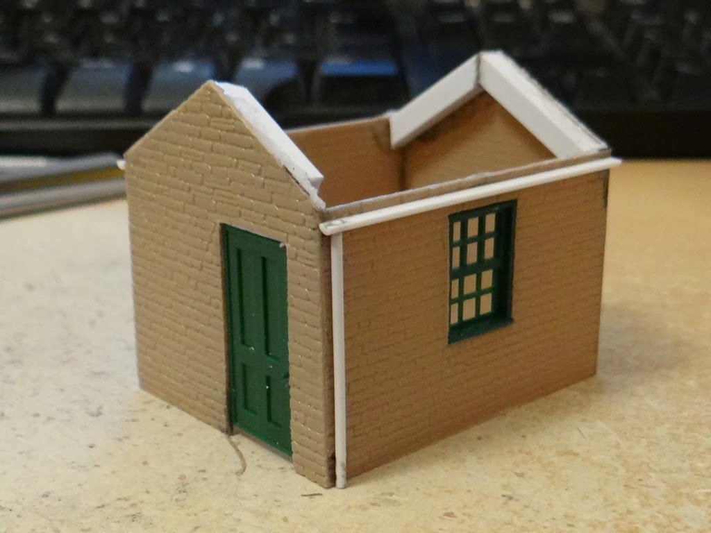
As a slight change from building locomotives and rolling stock I decided that I'd have a go at turning some of the 4mm scale Slater's embossed Plastikard that I bought back in July into a small building to see how well it worked and how exactly to use it. My original plan had been to build a cardboard shell and then to cover it in the plastikard as this would make a nice rigid structure. Unfortunately I suffered a severe cause of cowboy builder.

I spent quite a while drawing out the parts on the computer and made templates for the four walls in 2mm cardboard and then four walls in the plastikard to match. Unfortunately I managed to get the sizing wrong when going from the shell to the outer layer. Having cut out all 8 parts it was clear that they wouldn't go together, but it was also clear that the 2mm cardboard was too think for the wall depth I wanted, given the door and window parts I had to hand (these are from the PECO building components pack, part number LK-78). Rather than trying to redraw the cardboard shell I decided, given it was only a small test building, to just use the plastikard without any reinforcement. So I set about joining the walls together using plastic weld from E.M.A. Model Supplies.

I'm still amazed at just how strong a joint the plastic weld creates, and once all four walls were joined the structure is remarkably solid. While the window frame fitted nicely I decided I needed a little more depth to the door. This was easy to achieve by simply adding some 0.5mm plastruct strip around the door frame using more plastic weld (note to self: make sure the window is open wider next time you use this stuff). There is a gap under the door as I'm intending the bottom few millimeters of wall to be underground so the building won't appear to float.

The rest of the bits you can see are all more sections of plastruct. There are some 4mm square sections used as roof girders to thicken the side walls and give me somewhere to attach the roof. The gutter is 2mm half round and the drain pipe is 1.3mm rod; I drilled a hole in the half round and slotted the rod in to make a nice solid joint.

The next step is to sort the roof. I'm going to experiment with adding separate roof tiles so it might take a while, even though it is only a small roof. Once that's done it will be on to painting, which will hopefully hide some of the more cowboy builder aspects. For a first attempt it's ... well if I'm being honest fairly terrible. Terrible it may be but at least I'm learning things that will be useful for the next attempt.

Friday, May 23, 2014

Action at a Distance

So I've done a bit more work on the point control in that it will now actually throw an OO9 gauge point. This is achieved by attaching the servo arm to the point tie bar using some 0.5mm diameter piano wire running through some 2mm diameter aluminium tubing (both from Albion Alloys) to keep it in place; i.e. a proper wire-in-tube system.


Everything is currently just held down with double sided tape but that seems to hold well enough for experimentation. I could have glued the point down though as I won't be using it on the layout having damaged it beyond repair when soldering on the wires (one of the sleepers is so buckled that the switch rails don't line up so things derail) but it works for this purpose. I found using the second hole from the end of the servo arm and a rotation of 10 degrees was enough to nicely throw the point. The calibration was a bit hit and miss though so I need to work on the software on the Arduino to make that a bit more user friendly but so far I'm happy with how it is all working. If I can figure out how, I might slow down the action to be a bit more prototypical, although that might be tricky given that I'm still relying on the spring in the points to help complete the throw.

Next up will be checking that I've understood the frog switching wiring correctly by attaching the three wires from the point to the relay and checking for the expected power flow through the point.

Sunday, July 28, 2013

Stand On The Rock

Since the last time I showed you an overall view of the layout I've added quite a number of small details and done a little more painting, although I still haven't tackled the access road yet.

The main item of painting has involved colouring the rock outcrops. Given that I've assumed there will be quite a build up of soot and smoke on everything, I've made the rocks quite dark as well. They were painted with a mixture of stone gray and black liquid pigments from Woodland Scenics, and then washed over with a heavily watered down black to pick out all the cracks and crevices. They don't exactly blend in yet, but hopefully once I add grass, trees etc. it will look a little more natural.

The main new detail is the loading dock which incorporates a small crane. The base of the loading dock is also a painted rock face, the idea being that when the railway and factory were built they simply modified the existing landscape to suit their needs. The top surface is modelled as large paving stones (remember that N gauge is 2mm to the foot so each slab is about 2 foot by 1 foot in size) and was a rather laborious hand crafted process. Firstly I cut a piece of thin cardboard to the correct size. I then covered the cardboard in air drying modelling clay. Once dry I then used a cocktail stick to scratch out the joints between the stones. The whole thing was then painted using the same slate gray pigment as the rock faces, before a wash of black paint (not the liquid pigment) was used to bring out the detail. It might have taken quite a lot of work but I'm really happy with how it looks. Of course the first thing I did once it was in place was to drill a hole through it!

While a loading dock would clearly be helpful at the factory I decided to give the workers a further helping hand by fitting a small hand operated crane. This crane is built from a Ratio plastic kit for a yard crane, but I've left out the supplied base and steps (I was going to re-use the steps at the edge of the loading dock but they aren't quite the right size so I'll have to build something else). At the moment it is a little too shiny and new so will need weathering in, but I think it really adds to the scene, and even rotates properly so I can move it out of the way should I have larger wagons in the siding.

The other detail item fixed in the scene is the set of buffers you can just see at the end of the siding. These have actually appeared in a couple of photos on the blog already but I haven't actually mentioned them. Again these are built from a kit, specifically the Peco kit for rail built buffers. They are glued to the track and ensure that no matter how hard I try I can't run off the end of the siding (believe me I've tried, accidentally of course).