It's been six and a half years since I was first given the PH Designs kit to build Ivor the Engine and while the build process hasn't taken that entire period it has been long and involved. There have been a number of frustrating setbacks but I'm so glad I stuck with the kit as I'm over the moon with the finsihed model. Hopefully my enthusiasm comes through in this video looking at the finsihed model...
Showing posts with label OO Gauge. Show all posts
Showing posts with label OO Gauge. Show all posts
Wednesday, July 19, 2023

Monday, July 3, 2023
Lining Ivor
After all the fun with the large 16mm scale Hudson Hunslet I've switched back to doing some work on Ivor.
 Since we last saw the model I've added the chimney and water filler cap and painted in their brass sections along with the brass window surrounds. Having added those I sprayed the model with a gloss varnish (specifically Vallejo Mecha Varnish 26.701) using the airbrush. While I don't want the model to have a gloss finish this was so that I could have a nice shiny surface to paint on the lining.
Doing the lining has been the most difficult part of the painting so far. The lines are etched into the model and I was hoping I could just flood the lines with yellow paint. Unfortunately that didn't seem to work, mostly as the yellow paint was almost transparent and so didn't show up. In the end I mixed yellow and ivory paint together to give a thicker more opaque paint. This was then painted, fairly roughly, over the lines with the excess then wiped away using a wet cotton bud. I did have to do some of the lines a couple of times to get enough paint into the lines; mostly as some of the lines were quite shallow due to a build up of the green paint.
Looking at the model I'm really happy with how the lining has turned out. Clearly it wouldn't be appropriate for most locos, but for Ivor I think it's perfect, as the colour in the originals varies in both hue and intensity along the lines and between different shots and I think I've managed to capture that quite well.

Doing the lining has been the most difficult part of the painting so far. The lines are etched into the model and I was hoping I could just flood the lines with yellow paint. Unfortunately that didn't seem to work, mostly as the yellow paint was almost transparent and so didn't show up. In the end I mixed yellow and ivory paint together to give a thicker more opaque paint. This was then painted, fairly roughly, over the lines with the excess then wiped away using a wet cotton bud. I did have to do some of the lines a couple of times to get enough paint into the lines; mostly as some of the lines were quite shallow due to a build up of the green paint.
Looking at the model I'm really happy with how the lining has turned out. Clearly it wouldn't be appropriate for most locos, but for Ivor I think it's perfect, as the colour in the originals varies in both hue and intensity along the lines and between different shots and I think I've managed to capture that quite well.
Thursday, April 27, 2023
Ivor's Buffer Beams: So Many Options
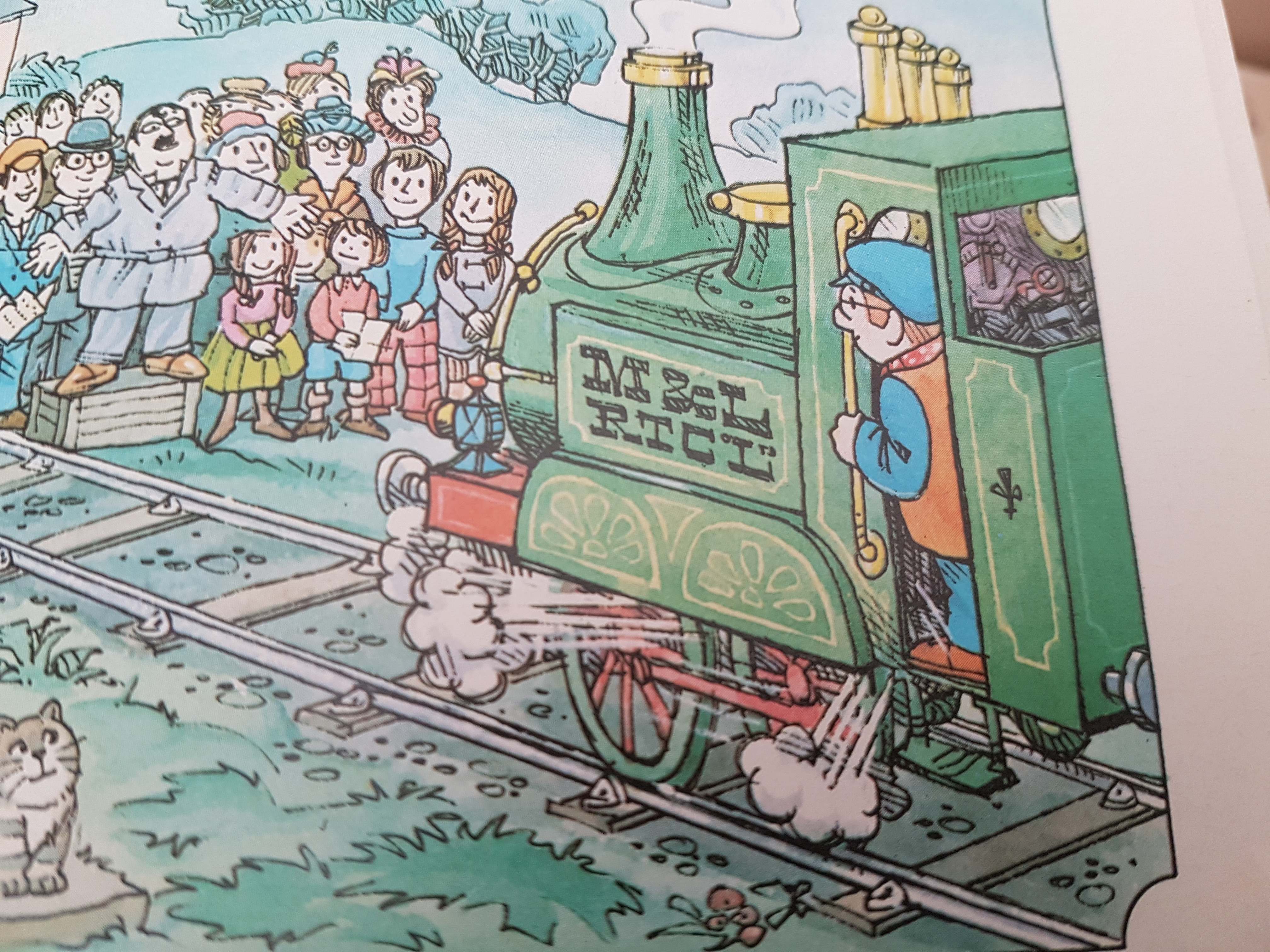
Having, put a base coat of green on Ivor I started looking thinking about painting the buffer beams. A quick glance at my standard reference work for this project, my childhood story book, and it quickly became clear that I had some decisions to make. The problem is that Ivor's buffer beams aren't coloured consistently throughout the book. From a thorough flick through it looks as if there are two options for the front and two for the rear.


 If we look across those three photos then you can see that.... for the rear buffer beam it's either red (as you might expect) or painted green the same as the body. For the front, you can see that while the front and sides are always red, the top surface is sometimes left green. Looking more closely I think the more common options, across the whole book, are for the front to be all red but the rear left green so that's what I've gone with.
 Of course it's also the easiest option as it meant I didn't have to try and get a perfectly horizontal masking line on the rear of the loco as there is no line in the etch between the back of the coal bunker and the buffer beam.



Wednesday, April 19, 2023
Back to the Top Left Hand Corner
With a little bit of sunshine appearing this afternoon I grabbed a few moments with the airbrush and.....
 Yes, Ivor is now green. It seems like an age since I last did anything with this model so it's nice to see the base coat on, especially as I'm happy with the colour now I can see it on the model. Phew!
I think the next step will be to mask up and paint the buffer beams and then maybe some of the detail paint work (like the rims around the windows). I'm in two minds about the exact ordering, as at some point I'm going to need to add some gloss varnish to some sections so that I can do the transfers and the lining, but I think that will be probably the last step before the final varnish coat and a light weathering..... unless anyone has a better suggestion for the order to do things?

I think the next step will be to mask up and paint the buffer beams and then maybe some of the detail paint work (like the rims around the windows). I'm in two minds about the exact ordering, as at some point I'm going to need to add some gloss varnish to some sections so that I can do the transfers and the lining, but I think that will be probably the last step before the final varnish coat and a light weathering..... unless anyone has a better suggestion for the order to do things?
Saturday, July 9, 2022
It Works, It Actually Works!
Having proved that the gearbox worked nicely under power it was time to finally fit it properly within the chassis. Doing so is amazingly fiddly as you have to get 7 parts all in alignment before you can slide the axle through: chassis frame, gearbox frame, washer, gear, washer, gearbox frame, and finally the other chassis frame. After a lot of swearing I eventually had this.
 Not that impressive I know given that it looks basically the same as before, especially given from this angle you can't see most of the gears. Anyway with everything in place there really was only one thing left to do..... apply some power!
After all the trouble I've had with this kit seeing it move for the first time was immensely satisfying; ignore the wheel slipping as that was just because of the drag from thw wires providing power as it doesn't yet have any pickups fitted.

After all the trouble I've had with this kit seeing it move for the first time was immensely satisfying; ignore the wheel slipping as that was just because of the drag from thw wires providing power as it doesn't yet have any pickups fitted.
Friday, June 17, 2022
It Rolls!
So after the apparent success of turning one working axle I had a go at making a second. Amazingly all went to plan, and more importantly they fit next to each other in the chassis.
 As you can see even with the smaller wheels than the instructions suggested there isn't a huge amount of clearance between the two axles.
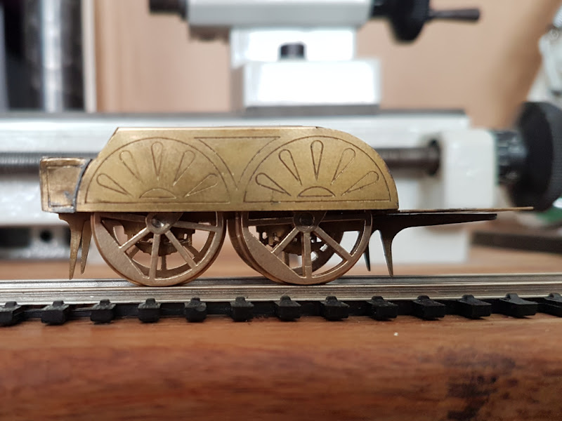 More importantly they also fit properly, albeit only just, within the splashers and it rolls!


Thursday, June 16, 2022
Two Wheels, One Axle
Having messed up the first attempt at axle making I spent some actual time thinking through the process a bit and came up with a plan. This essentially involved keeping a long piece of 1/8" axle steel nice and straight on the lathe using a fixed steady (a recent purcahse and this is the first time I've tried it) and then lightly makring the sections for an axle on the rod using the cutting tool. I could then cut the axle from the rod and face and turn with just the end protruding from the collet chuck. Unfortunately I forgot to take any photos while marking up the axles, but here you can see the end result (after I roughly cut the two sections from the rod).
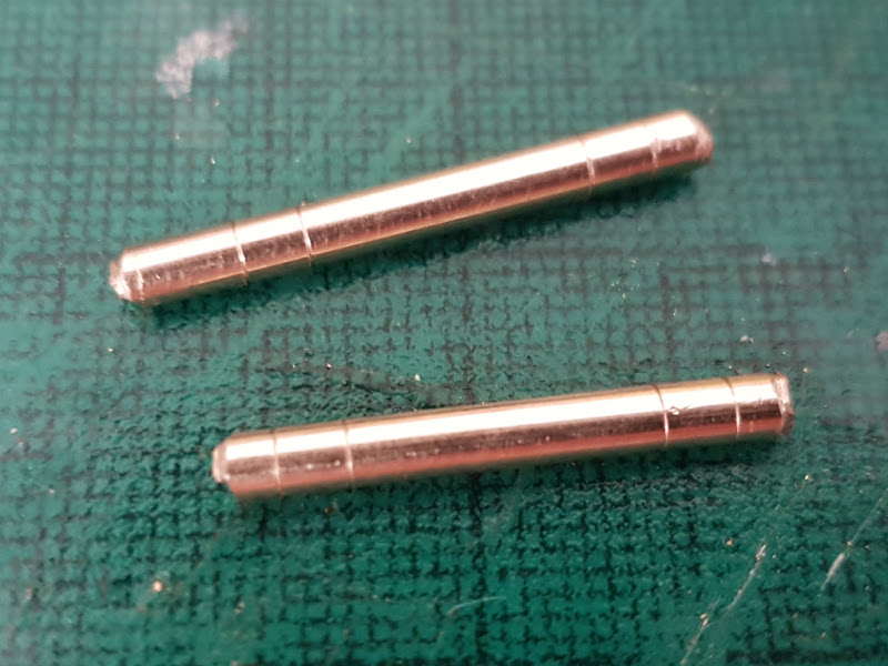 So if you look at those you can see I roughly cut them from the rod, so from each end I need to face off at the first line, and then turn down the rod between the first and second line. This will give me a stepped axle which should enforce the correct back-to-back measurement; although each end needs turning down differently to match the insulated and uninsulated wheels.
So far I've only managed to do one axle but......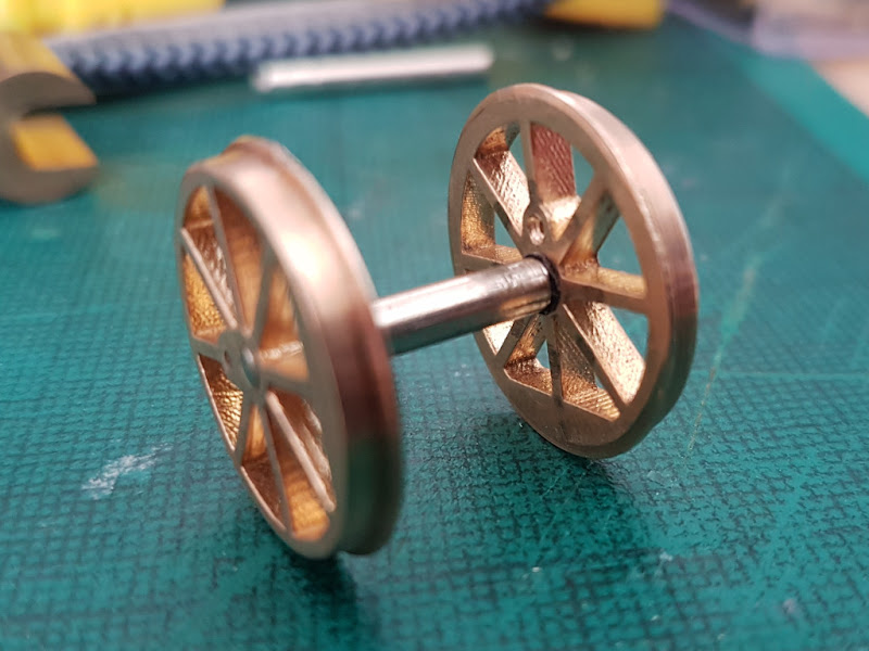 And just to prove that they both fit on track and roll
And you have no idea just how happy I am with that!

So far I've only managed to do one axle but......

And you have no idea just how happy I am with that!
Wednesday, June 8, 2022
Signs of Life
Given how sporadic, or none existant, posts have been over the last year or so I've no idea if anyone is still reading this blog, but believe it or not there are signs of some modelling happening!
Some of you may remember that for Christmas all the way back in 2016 I was bought a kit for building an OO guage model of Ivor the Engine. This was a nice present and the first from my then newly born son, Toby. Well Toby, is now five and a half, and I now have a second son, Thomas, who is 14 months old. What I don't have though is a completed model of Ivor the Engine.
The last time I blogged about the kit was almost four years ago in August of 2018 when everything had gone horribly wrong: I'd broken the wheel holding tool for my lathe and the wheels I had made, although correct to the instructions, didn't fit in the model. At that point I put the kit away in a box, never expecting it to be four years before it would appear again.
So where are we know? Well, fohrmann-WERKZEUGE were very helpful and sold me replacement parts for the wheel holding tool which saved me quite a bit of money over buying a complete replacement. Of course any money saved was then spent on having new set of wheels produced. These are essentially they same as last time (lost wax brass castings using 3D printed waxes all done through Shapeways) albeit slightly smaller to solve the main issue that arose with the originals.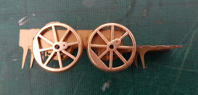 So far all I've done is separate the wheels and drill out the axle hole to 2mm, but as you can see roughly placing them against the chassis suggests that they will fit this time, especially given they will be fractionally smaller once I've turned them on the lathe to properly profile the edge and add the flange.
I've no idea when I'll get to do more work on the wheels but hopefully it won't take four years before there is more to report.
Some of you may remember that for Christmas all the way back in 2016 I was bought a kit for building an OO guage model of Ivor the Engine. This was a nice present and the first from my then newly born son, Toby. Well Toby, is now five and a half, and I now have a second son, Thomas, who is 14 months old. What I don't have though is a completed model of Ivor the Engine.
The last time I blogged about the kit was almost four years ago in August of 2018 when everything had gone horribly wrong: I'd broken the wheel holding tool for my lathe and the wheels I had made, although correct to the instructions, didn't fit in the model. At that point I put the kit away in a box, never expecting it to be four years before it would appear again.
So where are we know? Well, fohrmann-WERKZEUGE were very helpful and sold me replacement parts for the wheel holding tool which saved me quite a bit of money over buying a complete replacement. Of course any money saved was then spent on having new set of wheels produced. These are essentially they same as last time (lost wax brass castings using 3D printed waxes all done through Shapeways) albeit slightly smaller to solve the main issue that arose with the originals.

I've no idea when I'll get to do more work on the wheels but hopefully it won't take four years before there is more to report.
Tuesday, August 14, 2018
Insulated Driving Wheels: An Experiment
While the build of Ivor might be on hiatus, I now have four wheels which are effectively scrap (given that they are no no longer the same size) on which it is safe to experiment. The final two pieces of the wheel design I needed to finalise were the insulation from the axle and the crank pin.


Let's start with the insulation first. It's difficult to see in the photos but what I've done is to simply take the test axle from a few posts back and fit this to one of the wheels. This involved opening out the axle hole in the wheel to 2.8mm which is a nice tight fit for the insulating bush I took from a pair of hornby disc wheels. I'm not sure this is the final way I'll go (I might try turning my own insulating bushes) but it is nice and straightforward and seems to adequately insulate the wheels from the axle at little effort or expense. Obviously on the real wheel I'd trim the axle back to the face of the wheel.
When I was originally working on the 3D model for the wheels my plan was to use a 14BA screw as the crankpin with a hole through the wheel tapped for 14BA so the screw would actually screw into the wheel. I had wanted to cast a recess into the back of the wheel to seat the cheesehead bolt but the wall thickness requirements meant that wasn't possible. So my plan was to screw the bolt into the wheel and then cut the head flush with the back. A little drop of loctite helping to hold the bolt in place. Unfortunately while I managed to open out the hole big enough to tap, I then broke one of my 14BA taps and stripped the cutting threads from another. With no taps left I opened the hole up slightly further so that the bolt was a tight sliding fit. Rather than holding it in place just with loctite on the body of the bolt I decided to drill a recess for the bolt head anyway as there seemed to be enough material. With that done the bolt sits nicely in the back of the wheel and the bolt head helps to keep the bolt perpendicular to the wheel while also providing more surface area for loctite to hold it in place. Once the loctite had set I did try pushing the crankpin out and couldn't do it by hand. Even with a set of pliers it took a lot of force to break the seal, so this definitely looks like a workable solution.


Let's start with the insulation first. It's difficult to see in the photos but what I've done is to simply take the test axle from a few posts back and fit this to one of the wheels. This involved opening out the axle hole in the wheel to 2.8mm which is a nice tight fit for the insulating bush I took from a pair of hornby disc wheels. I'm not sure this is the final way I'll go (I might try turning my own insulating bushes) but it is nice and straightforward and seems to adequately insulate the wheels from the axle at little effort or expense. Obviously on the real wheel I'd trim the axle back to the face of the wheel.
When I was originally working on the 3D model for the wheels my plan was to use a 14BA screw as the crankpin with a hole through the wheel tapped for 14BA so the screw would actually screw into the wheel. I had wanted to cast a recess into the back of the wheel to seat the cheesehead bolt but the wall thickness requirements meant that wasn't possible. So my plan was to screw the bolt into the wheel and then cut the head flush with the back. A little drop of loctite helping to hold the bolt in place. Unfortunately while I managed to open out the hole big enough to tap, I then broke one of my 14BA taps and stripped the cutting threads from another. With no taps left I opened the hole up slightly further so that the bolt was a tight sliding fit. Rather than holding it in place just with loctite on the body of the bolt I decided to drill a recess for the bolt head anyway as there seemed to be enough material. With that done the bolt sits nicely in the back of the wheel and the bolt head helps to keep the bolt perpendicular to the wheel while also providing more surface area for loctite to hold it in place. Once the loctite had set I did try pushing the crankpin out and couldn't do it by hand. Even with a set of pliers it took a lot of force to break the seal, so this definitely looks like a workable solution.
Friday, August 10, 2018
Determining the Wheel Diameter
I've been having a bit more of a think about the wheels for Ivor after yesterdays discovery that they are probably too big to both fit inside the splashers and next to each other. It's also been pointed out to me that, normally the centre line of the buffer on standard gauge stock sits 3' 6" above rail height, which would be 14mm in 4mm to the foot scale. While Ivor isn't exactly based on a real loco, it would still be useful to have him sit at roughly the right height if I don't want him to look daft against standard 4mm wagon kits etc. The upshot of this is that I've been doing some maths...

The upshot of all that is summarised in the bottom right hand corner. My original 21mm diameter wheels would put the centre line of the buffer at 14.5875mm above rail head, so about 0.6mm (or almost 2" in real life) too high. To get it to sit at exactly 14mm I need the wheels to be 19.825mm in diameter (excluding the flanges).
I think given this bit of maths (and if anyone fancies checking my working it would be most appreciated) that I would be better off reducing the wheels to 20mm (or 5' in real life rather than the suggested 5'3") which would give a total diameter including the flange of 21.27mm which given the wheelbase of 22.5mm should leave a gap of 1.23mm between the flanges of the two wheels.
Does that seem sensible to everyone?
The upshot of all that is summarised in the bottom right hand corner. My original 21mm diameter wheels would put the centre line of the buffer at 14.5875mm above rail head, so about 0.6mm (or almost 2" in real life) too high. To get it to sit at exactly 14mm I need the wheels to be 19.825mm in diameter (excluding the flanges).
I think given this bit of maths (and if anyone fancies checking my working it would be most appreciated) that I would be better off reducing the wheels to 20mm (or 5' in real life rather than the suggested 5'3") which would give a total diameter including the flange of 21.27mm which given the wheelbase of 22.5mm should leave a gap of 1.23mm between the flanges of the two wheels.
Does that seem sensible to everyone?
Thursday, August 9, 2018
Is It Just Me?
I'm beginning to wonder if either I'm drawn to kits with design issues, or if I'm just not very good at building kits accurately.
Having finally battled all that was weird and wonderful with the Canopus kit I thought the kit for Ivor the Engine looked quite a bit easier. Okay I made life more complex for myself by deciding to make my own wheels, but in itself that shouldn't affect the design of the kit. Having built up the chassis (fairly easily I may add) I've now made a start on the body, which in turn has led me to discover a couple of, potentially, catastrophic issues.

So far I've formed the splashers and attached them to the footplate, which also includes the front buffer beam. What you can see, in the photo above, is the chassis slotted into the footplate containing one of my wheels on the test axle I turned.
The first problem was that the chassis wouldn't fit into the footplate as it was slightly two long. After a lot of careful filing I've made it fit and the fixing holes appear to line up pretty well. The second problem though is that the chassis wouldn't fit with the wheels attached. In the photos you can see that I've bent the front of the splashers that are inside the model to get the wheel to fit, and it still feels like it's catching when I turn the wheel. I think the solution to this will be to cut away the extra metal, as it can't be seen once the model is assembled, and isn't needed to keep the chassis central once the screws are in place. Before doing that though I wanted to figure out why the wheels didn't fit.
Looking again at the instructions, which are just a sequence of photos with no textual description, I think all the photos show the 7mm version of the kit and not the 4mm version. It's difficult to be sure as most of the photos don't include anything to give a sense of scale, but they all seem to have previously appeared in this RMWeb thread discussing the build of the 7mm kit. The one page that is clearly for 4mm gives the size of the finished model and is the place where it suggests to use Ultrscale OR Markits 5'3" 16 spoke wheels with 8 spokes removed. As I was making my own wheels I took the 5'3" as a starting point and produced 21mm wheels (5.25*4). As I made the wheels to RP25-110 the flange depth is 0.025" or 0.635 giving a total wheel diameter of 22.27mm. The instruction page also states that the wheelbase is 22.50mm which as far as I'm concerned is just a bit too close to 22.27mm for comfort. In fact placing two wheels against the chassis I'm not sure they will fit without the flanges touching!
Reading through the thread on RMWeb I did notice that the suggested wheels in 7mm scale are actually 5'2" diameter not 5'3". I know that would only change their diameter by a small amount (they would be 21.94mm over the flanges) but that extra clearance would probably be great for both the splashers and between the wheels.
I can't be sure that the flanges will touch until I turn up a second axle (I've just the test axle so far) but if they do then I guess I'm going to have to try and reduce them in size slightly which is a real pain, although it might mean I can remove the slight flats on the flange from removing the wheels from the sprue. Mind you that isn't really the point; if I'm following the instructions for a kit am I just picking kits with issues, or am I just not assembling them accurately enough?
Having finally battled all that was weird and wonderful with the Canopus kit I thought the kit for Ivor the Engine looked quite a bit easier. Okay I made life more complex for myself by deciding to make my own wheels, but in itself that shouldn't affect the design of the kit. Having built up the chassis (fairly easily I may add) I've now made a start on the body, which in turn has led me to discover a couple of, potentially, catastrophic issues.

So far I've formed the splashers and attached them to the footplate, which also includes the front buffer beam. What you can see, in the photo above, is the chassis slotted into the footplate containing one of my wheels on the test axle I turned.
The first problem was that the chassis wouldn't fit into the footplate as it was slightly two long. After a lot of careful filing I've made it fit and the fixing holes appear to line up pretty well. The second problem though is that the chassis wouldn't fit with the wheels attached. In the photos you can see that I've bent the front of the splashers that are inside the model to get the wheel to fit, and it still feels like it's catching when I turn the wheel. I think the solution to this will be to cut away the extra metal, as it can't be seen once the model is assembled, and isn't needed to keep the chassis central once the screws are in place. Before doing that though I wanted to figure out why the wheels didn't fit.
Looking again at the instructions, which are just a sequence of photos with no textual description, I think all the photos show the 7mm version of the kit and not the 4mm version. It's difficult to be sure as most of the photos don't include anything to give a sense of scale, but they all seem to have previously appeared in this RMWeb thread discussing the build of the 7mm kit. The one page that is clearly for 4mm gives the size of the finished model and is the place where it suggests to use Ultrscale OR Markits 5'3" 16 spoke wheels with 8 spokes removed. As I was making my own wheels I took the 5'3" as a starting point and produced 21mm wheels (5.25*4). As I made the wheels to RP25-110 the flange depth is 0.025" or 0.635 giving a total wheel diameter of 22.27mm. The instruction page also states that the wheelbase is 22.50mm which as far as I'm concerned is just a bit too close to 22.27mm for comfort. In fact placing two wheels against the chassis I'm not sure they will fit without the flanges touching!
Reading through the thread on RMWeb I did notice that the suggested wheels in 7mm scale are actually 5'2" diameter not 5'3". I know that would only change their diameter by a small amount (they would be 21.94mm over the flanges) but that extra clearance would probably be great for both the splashers and between the wheels.
I can't be sure that the flanges will touch until I turn up a second axle (I've just the test axle so far) but if they do then I guess I'm going to have to try and reduce them in size slightly which is a real pain, although it might mean I can remove the slight flats on the flange from removing the wheels from the sprue. Mind you that isn't really the point; if I'm following the instructions for a kit am I just picking kits with issues, or am I just not assembling them accurately enough?
Monday, August 6, 2018
RP25-110
Next up in the sage of making wheels for Ivor is the bit I've been dreading the most; profiling the wheels to add the flange. In theory this should be easy as in essence all it involves is reducing the diameter of the casting using a profiling tool, but that glosses over a whole bunch of issues.
Let's start by defining exactly what we mean by "to profile" a wheel. Put simply it's to shape the tread and flange of the wheel to a specific shape. There are lots of different profiles all defined by different guidelines and associations. For Ivor I've settled on using wheels profiled to match RP25-110. This means I'm using the RP25 profile, as defined by the NMRA, with code 110 wheels, i.e. wheels that are 0.110" in depth (or for those who prefer metric, 2.794mm). Now a lot of the work of making the wheels fit this profile was done during the design of the 3D model as it set the depth etc. but it is impossible to 3D print thin enough and accurately enough to produce the flange.
To add the flange (and to ensure a nice smooth turned tread) I'm going to finish the wheel profile on the lathe, using a specific profiling tool. You can get profiling tools from numerous places but I picked up this one from Carbide Solutions as it had a square shank which made mounting it in the lathe easy.
Even with a sharp profiling tool (I'd not used mine before) this is actually quite hard work for the lathe and involved taking very very tiny cuts and quite a few breaks even during each wheel to ensure I didn't over heat the lathe or the wheel (it got exceptionally hot).

As you can see I've held the wheel in the lathe using a tool designed specifically for the job (another purchase from fohrmann-WERKSEUGE). The tool ensures the wheel is perpendicular to the lathe bed and clamped tight, although I did manage to over tighten the clamp on two out of the four wheels which unfortunately opened out the axle hole in the wheels slightly -- not a problem as I'll fit insulating bushes to these two wheels so will need to open the hole further anyway.
You'll also notice that I've left as little of the profiling tool hanging out of the toolpost as possible to try and reduce chatter, and I clamped the crossslide tight so as to remove as many sources of movement as possible. On the first wheel I started with the lathe on a slow speed but that was a disaster as the tool tended to dig in and bounce around, even with the lathe locked as solid as possible. I reconfigured the belts to run the lathe on it's fastest setting (4000 rpm) and with very very tiny cuts this worked a lot better, and fortunately I figured this out before destroying the first wheel. Once I'd reduced the first wheel to the correct diameter (21mm for 5' 3" wheels at 4mm to the foot) I took a note of the position on the cross slide, and then repeated the process for the other three wheels.

It took me all morning (in blocks of a couple of minutes here and there) but I've managed to profile all four wheels. While I'm not going to claim any of the four as perfect, I'm happy enough with them all to try and assemble the loco. All four have a difference of no more than 0.02mm when measured and all are slightly above 21mm rather than below, so they are close enough that I think they should sit level. The main issue with them is that when I removed them from the sprue, and filed the excess away, I didn't take into account that the edge of the flange was the edge of the casting (something I'll change if I produce any more) and so in a couple of places there is a slight straight edge on the flange, but hopefully not enough to cause a problem, if it is I can always order another set and replace them but fingers crossed...
Let's start by defining exactly what we mean by "to profile" a wheel. Put simply it's to shape the tread and flange of the wheel to a specific shape. There are lots of different profiles all defined by different guidelines and associations. For Ivor I've settled on using wheels profiled to match RP25-110. This means I'm using the RP25 profile, as defined by the NMRA, with code 110 wheels, i.e. wheels that are 0.110" in depth (or for those who prefer metric, 2.794mm). Now a lot of the work of making the wheels fit this profile was done during the design of the 3D model as it set the depth etc. but it is impossible to 3D print thin enough and accurately enough to produce the flange.
To add the flange (and to ensure a nice smooth turned tread) I'm going to finish the wheel profile on the lathe, using a specific profiling tool. You can get profiling tools from numerous places but I picked up this one from Carbide Solutions as it had a square shank which made mounting it in the lathe easy.
Even with a sharp profiling tool (I'd not used mine before) this is actually quite hard work for the lathe and involved taking very very tiny cuts and quite a few breaks even during each wheel to ensure I didn't over heat the lathe or the wheel (it got exceptionally hot).

As you can see I've held the wheel in the lathe using a tool designed specifically for the job (another purchase from fohrmann-WERKSEUGE). The tool ensures the wheel is perpendicular to the lathe bed and clamped tight, although I did manage to over tighten the clamp on two out of the four wheels which unfortunately opened out the axle hole in the wheels slightly -- not a problem as I'll fit insulating bushes to these two wheels so will need to open the hole further anyway.
You'll also notice that I've left as little of the profiling tool hanging out of the toolpost as possible to try and reduce chatter, and I clamped the crossslide tight so as to remove as many sources of movement as possible. On the first wheel I started with the lathe on a slow speed but that was a disaster as the tool tended to dig in and bounce around, even with the lathe locked as solid as possible. I reconfigured the belts to run the lathe on it's fastest setting (4000 rpm) and with very very tiny cuts this worked a lot better, and fortunately I figured this out before destroying the first wheel. Once I'd reduced the first wheel to the correct diameter (21mm for 5' 3" wheels at 4mm to the foot) I took a note of the position on the cross slide, and then repeated the process for the other three wheels.

It took me all morning (in blocks of a couple of minutes here and there) but I've managed to profile all four wheels. While I'm not going to claim any of the four as perfect, I'm happy enough with them all to try and assemble the loco. All four have a difference of no more than 0.02mm when measured and all are slightly above 21mm rather than below, so they are close enough that I think they should sit level. The main issue with them is that when I removed them from the sprue, and filed the excess away, I didn't take into account that the edge of the flange was the edge of the casting (something I'll change if I produce any more) and so in a couple of places there is a slight straight edge on the flange, but hopefully not enough to cause a problem, if it is I can always order another set and replace them but fingers crossed...
Thursday, August 2, 2018
Flangeless Wheels
Having checked that I could machine the silver steel rod to make axles I've turned my attention to the actual wheels. I've actually been working on these for a while now. The main problem I had is... what do Ivor's wheels look like? While they always seem to have the same number of spokes they seem to differ slightly from scene to scene, mostly around the thickness of spokes. However, in some shots the wheels have balance weights and in some they don't. In the end I decided to work from a specific drawing in my childhood book.

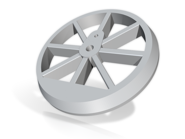
The plan was to make a 3D model of the wheel, bulked out in diameter slightly. These would then be printed in brass, and then finished on the lathe using a profiling tool. So far I've designed the model (see above), had them printed as a sprue of four wheels (cheaper than printing each separately) and separated the wheels from the sprue.

Next up will be drilling out the central hole for the axle and using a profiling tool to reduce the diameter slightly and add the flange.


The plan was to make a 3D model of the wheel, bulked out in diameter slightly. These would then be printed in brass, and then finished on the lathe using a profiling tool. So far I've designed the model (see above), had them printed as a sprue of four wheels (cheaper than printing each separately) and separated the wheels from the sprue.

Next up will be drilling out the central hole for the axle and using a profiling tool to reduce the diameter slightly and add the flange.
Stepped Axles
Having assembled the basic chassis the next step is to figure out the wheels. Unfortunately as the prototype is a cartoon character there aren't any wheel sets I can just buy off the shelf. The only suggestion in the instructions is to use "Ultrascale or Markits 5'3" 16 spoke wheels with 8 spokes removed". Having looked at both of these options I wasn't happy with either, as even with the extra spokes removed I didn't think they really matched up with those you see in the cartoons. In the end the only thing I could think of was to make my own wheels. Clearly this isn't going to be a quick and simple process so it's likely to go on for quit a few posts as I detail the different steps and experiments. In this post I'm going to concentrate on the axles.
As I mentioned previously the kit is designed for use with axles with a diameter of 1/8". The wheels on Ivor don't have a huge central boss, and certainly not something big enough to accommodate a 1/8" (or bigger for an insulating bush) hole so my plan is to use stepped axles. Most wheels seems to use steel for axles so I've bought some 1/8" diameter silver steel rod (from Eileens Emporium) but having never tried to turn anything other than soft brass rod (CZ121 brass to be precise) I had no idea how well this would work.


For a quick experiment I've turned down a short length of the silver steel rod to take one of the OO gauge wheels I used to build the Clayton. These wheels fitted on a 2mm axle so I had to remove roughly 1.25mm from the diameter of the rod. I actually found machining the silver steel possibly easier than brass and the turnings come off as long thing ribbons rather than lots of dust. All told (including setting up the lathe) this took about 10 minutes. Now obviously machining steps on both ends of an axle and getting the back-to-back correct is going to be more time consuming but at least now I know I can work with the materials I've got, and I've 26" of rod (minus the short test piece) to play with and I only need two short (approximately 19mm) axles.
As I mentioned previously the kit is designed for use with axles with a diameter of 1/8". The wheels on Ivor don't have a huge central boss, and certainly not something big enough to accommodate a 1/8" (or bigger for an insulating bush) hole so my plan is to use stepped axles. Most wheels seems to use steel for axles so I've bought some 1/8" diameter silver steel rod (from Eileens Emporium) but having never tried to turn anything other than soft brass rod (CZ121 brass to be precise) I had no idea how well this would work.


For a quick experiment I've turned down a short length of the silver steel rod to take one of the OO gauge wheels I used to build the Clayton. These wheels fitted on a 2mm axle so I had to remove roughly 1.25mm from the diameter of the rod. I actually found machining the silver steel possibly easier than brass and the turnings come off as long thing ribbons rather than lots of dust. All told (including setting up the lathe) this took about 10 minutes. Now obviously machining steps on both ends of an axle and getting the back-to-back correct is going to be more time consuming but at least now I know I can work with the materials I've got, and I've 26" of rod (minus the short test piece) to play with and I only need two short (approximately 19mm) axles.
Wednesday, August 1, 2018
In the Top-Left Hand Corner.....
You may remember that back at Christmas 2016 one of my presents was the OO gauge kit from PH Designs for Ivor the Engine. It's taken me a while but I've now made a start on assembling the kit.

The first step was to separate the main chassis component from the etch and then solder bearings into the frames. The kit is designed to use wheels with 1/8" axles but the 1/8" bearings I already had wouldn't fit in the holes in the frames as the walls of the bearings were way too thick. As you can seem I'm using a set of bearings from Nairnshire Modelling Supplies which fit perfectly within the etch.

There were some odd issues with little tags on the etches (not where the tabs hold the part to the fret but elsewhere, almost as if it hadn't etched properly) but in general the cleanup was easy and the bearings soldered into place without incident. I did have a bit of an issue when folding the chassis though. While folding down the frames was easy enough, and two lengths of 1/8" silver steel rod kept everything square, it was impossible to get the step down at the back of the chassis to fit properly. In the end I snapped off the final part of the fold, reduced the length ever so slightly and then soldered it back into place -- hence the slightly messy solder joint. It might just be that I didn't quite get the fold right in the middle of the line (quite wide fold lines) rather than an issue with the part itself. Anyway so far so good.
Next up will be sorting out the wheels...

The first step was to separate the main chassis component from the etch and then solder bearings into the frames. The kit is designed to use wheels with 1/8" axles but the 1/8" bearings I already had wouldn't fit in the holes in the frames as the walls of the bearings were way too thick. As you can seem I'm using a set of bearings from Nairnshire Modelling Supplies which fit perfectly within the etch.

There were some odd issues with little tags on the etches (not where the tabs hold the part to the fret but elsewhere, almost as if it hadn't etched properly) but in general the cleanup was easy and the bearings soldered into place without incident. I did have a bit of an issue when folding the chassis though. While folding down the frames was easy enough, and two lengths of 1/8" silver steel rod kept everything square, it was impossible to get the step down at the back of the chassis to fit properly. In the end I snapped off the final part of the fold, reduced the length ever so slightly and then soldered it back into place -- hence the slightly messy solder joint. It might just be that I didn't quite get the fold right in the middle of the line (quite wide fold lines) rather than an issue with the part itself. Anyway so far so good.
Next up will be sorting out the wheels...
Monday, January 23, 2017
Ivor the Engine
As I predicated in the previous post I've not really had much time for modelling over the last thirteen weeks. I've no idea when this will change, but when it does I'll have another project to start on...
Obviously Toby isn't old enough to be choosing Christmas presents for people yet, but Bryony and I thought it would be nice if we each had a present from him at his 1st Christmas that wasn't at all baby related and that would give us something fun to do when we eventually have some free time for hobbies again. Bryony got a very nice hand turned yarn bowl and I got a kit to build Ivor the Engine.
I've fancied building Ivor for a few years ever since Paul pointed out that PH Designs did a kit for a 7mm scale model. Since then they have also released the kit in 4mm scale; actually two kits one for OO gauge, which I've got, and one for EM/P4 for those who like a more accurate track gauge.
What you get in the "kit" is the etches and a sheet of transfers leaving you to source wheels, motor, gearbox, and boiler fittings; not really what I'd call a kit. To make matters worse the recommended motor is the Mashima 1015 and Mashima motors aren't made any more, plus the instructions don't list a specific gearbox as far as I can see. Finally there aren't any wheels that are a perfect match so those suggested in the kit require cutting up to produce the correct number of spokes, and therein lies another problem.

As you can see I've been collecting together some prototype reference material ready to help with the build. This includes the storybook I've had since I was a child and some stills taken from the DVD of the complete series (all the colour episodes anyway). It turns out that the book and TV series are a little inconsistent, especially when it comes to the wheels. In the TV series Ivor appears to have wheels with six spokes, whereas the wheels clearly have eight spokes in the book. It gets even more confusing as some shots, in both the TV episodes and the book, show balance weights on the wheels while some don't.
So while I'm sure it's going to be a fun build, when I eventually have the time, it's clear there are a few issues to sort first, namely which motor, gearbox, and wheels to use. If anyone has any thoughts or suggestions I'd be grateful if you left a comment.
Obviously Toby isn't old enough to be choosing Christmas presents for people yet, but Bryony and I thought it would be nice if we each had a present from him at his 1st Christmas that wasn't at all baby related and that would give us something fun to do when we eventually have some free time for hobbies again. Bryony got a very nice hand turned yarn bowl and I got a kit to build Ivor the Engine.
I've fancied building Ivor for a few years ever since Paul pointed out that PH Designs did a kit for a 7mm scale model. Since then they have also released the kit in 4mm scale; actually two kits one for OO gauge, which I've got, and one for EM/P4 for those who like a more accurate track gauge.
What you get in the "kit" is the etches and a sheet of transfers leaving you to source wheels, motor, gearbox, and boiler fittings; not really what I'd call a kit. To make matters worse the recommended motor is the Mashima 1015 and Mashima motors aren't made any more, plus the instructions don't list a specific gearbox as far as I can see. Finally there aren't any wheels that are a perfect match so those suggested in the kit require cutting up to produce the correct number of spokes, and therein lies another problem.

As you can see I've been collecting together some prototype reference material ready to help with the build. This includes the storybook I've had since I was a child and some stills taken from the DVD of the complete series (all the colour episodes anyway). It turns out that the book and TV series are a little inconsistent, especially when it comes to the wheels. In the TV series Ivor appears to have wheels with six spokes, whereas the wheels clearly have eight spokes in the book. It gets even more confusing as some shots, in both the TV episodes and the book, show balance weights on the wheels while some don't.
So while I'm sure it's going to be a fun build, when I eventually have the time, it's clear there are a few issues to sort first, namely which motor, gearbox, and wheels to use. If anyone has any thoughts or suggestions I'd be grateful if you left a comment.
Saturday, January 11, 2014
Loss Leader

On Thursday I couldn't resist picking up a copy of the February issue of Railway Modeller. As well as a number of interesting layout descriptions, there is an intriguing article on making coaches by printing the full colour coach sides, and then there is the free gift: an OO gauge Lineside Hut kit from Ratio. Now I know that the magazine is published by Peco who own Ratio and so they won't have been paying full price for the kits, but I still think they must be losing money on each magazine sold. According to the website of my local model shop the lineside hut kit costs £5.50, yet the magazine only costs £3.95. If they are making any profit at all it has to be just a few pence!
While I'm not currently modelling in OO I also haven't built many plastic kits in a long time (as a kid I used to build Airfix aeroplanes, and I've recently built two Parkside Dundas wagons), so it will be a fun diversion, and I can try out some new painting and modelling techniques without worrying about making a mess of a model I really need. All in all I think buying the magazine this month was money well spent.
Wednesday, November 20, 2013
L&YR 2-4-2T No. 1008
When I visted Barrow Hill back in September, one of the things I blogged about were the new and upcoming releases from Bachmann that were on display. Of particular interest to me was the 2-4-2T that John Aspinal designed for the Lancashire and Yorkshire Railway. On my recent trip to the National Railway Museum I managed to photograph the only preserved member of the class, number 1008.


According to Barry C. Lane's excellent book on the L&YR, number 1008 was actually the first of the type to be built and entered service in February of 1889. It was renumbered as 10621 when the L&YR became part of LMS and then 50621 under BR ownership before eventually being withdrawn in September of 1954. As far as I can tell she is currently displayed with her as built livery, as the front buffer beam includes the locomotives number and this practice didn't continue after the middle of 1891.
I really like this locomotive and I think, had more been preserved, they would have been an ideal size for working passenger services on many of the UK's preserved railways. As it is, if we want to see this locomotive move then we will have to make do with a model, and while space constraints have left me currently modelling in N gauge, I couldn't resist this exquisite OO gauge model.

As I mentioned in a previous post the Bachmann model will be widely available in a number of liveries (which will be available some time next year I believe) but the L&YR liveried model is exclusive to Locomotion Models (the modelling arm of the National Railway Museum). Given that only 500 models were being made in this livery I pre-ordered mine at the earliest opportunity. If I never go back to modelling in OO then a mint condition boxed example should keep its resale value so I'm considering it a good investment come what may.
I don't currently have the space to even temporarily lay out an oval of OO gauge track so I can't tell you anything about the running qualities of the model, but I can tell you that as a static model it is superb. I'm not even sure that a rivet counter would find much to complain about with this model. I've taken some detail shots (yes I should have dusted first) so you can get a sense of just how good it is.


If I had to find something to complain about then, for the price of the model, etched brass number plates would have been nice, especially given that I know they are possible to produce, but the printing of the number plate detail is so crisp and well applied that from a distance you wouldn't know they weren't etched. What truly amazes me is the level of detail included on areas that are impossible to see when in use; the leaf springs behind the driving wheels being the main example (bottom right picture) as these can't be seen when the train is on the track.
All in all an exquisite model of a wonderful locomotive. If you want one in L&YR livery then hurry over to Locomotion Models because as of this moment there are only 11 left and I doubt they will be available for long.


According to Barry C. Lane's excellent book on the L&YR, number 1008 was actually the first of the type to be built and entered service in February of 1889. It was renumbered as 10621 when the L&YR became part of LMS and then 50621 under BR ownership before eventually being withdrawn in September of 1954. As far as I can tell she is currently displayed with her as built livery, as the front buffer beam includes the locomotives number and this practice didn't continue after the middle of 1891.
I really like this locomotive and I think, had more been preserved, they would have been an ideal size for working passenger services on many of the UK's preserved railways. As it is, if we want to see this locomotive move then we will have to make do with a model, and while space constraints have left me currently modelling in N gauge, I couldn't resist this exquisite OO gauge model.

As I mentioned in a previous post the Bachmann model will be widely available in a number of liveries (which will be available some time next year I believe) but the L&YR liveried model is exclusive to Locomotion Models (the modelling arm of the National Railway Museum). Given that only 500 models were being made in this livery I pre-ordered mine at the earliest opportunity. If I never go back to modelling in OO then a mint condition boxed example should keep its resale value so I'm considering it a good investment come what may.
I don't currently have the space to even temporarily lay out an oval of OO gauge track so I can't tell you anything about the running qualities of the model, but I can tell you that as a static model it is superb. I'm not even sure that a rivet counter would find much to complain about with this model. I've taken some detail shots (yes I should have dusted first) so you can get a sense of just how good it is.


If I had to find something to complain about then, for the price of the model, etched brass number plates would have been nice, especially given that I know they are possible to produce, but the printing of the number plate detail is so crisp and well applied that from a distance you wouldn't know they weren't etched. What truly amazes me is the level of detail included on areas that are impossible to see when in use; the leaf springs behind the driving wheels being the main example (bottom right picture) as these can't be seen when the train is on the track.
All in all an exquisite model of a wonderful locomotive. If you want one in L&YR livery then hurry over to Locomotion Models because as of this moment there are only 11 left and I doubt they will be available for long.
Tuesday, November 19, 2013
EM1
When it comes to railways I'm definitely a steam person. In fact I've yet to find a diesel or electric locomotive that inspires me in any fashion. Having said that I am, however, also interested in the history of the line that runs along the bottom of the garden and so I'll make an exception for the EM1. The EM1, which stands for Electric Mixed-Traffic 1, was specifically designed and built for the Woodhead line. They were powered from 1.5 kV DC overhead catenary and employed regenerative breaking to actually feed power back into the system when running downhill. They were predominately used for working freight trains through Penistone as this photo from 1955 shows.


The photo shows number 26020 which coincidentally is the only preserved member of the class and which I photographed at the National Railway Museum when I visited for The Great Gathering.
If you want more details on the EM1 then Wikipedia has a fairly informative page, and if you fancy one in model form then Heljan produce an OO gauge model exclusively for Olivia's Trains.

The photo shows number 26020 which coincidentally is the only preserved member of the class and which I photographed at the National Railway Museum when I visited for The Great Gathering.
If you want more details on the EM1 then Wikipedia has a fairly informative page, and if you fancy one in model form then Heljan produce an OO gauge model exclusively for Olivia's Trains.
Tuesday, October 8, 2013
Coming Soon...
I mentioned before that there was very little trade at this years Barrow Hill Live. This did mean that I managed to leave without buying anything, although having looked at the Bachmaan display I have a feeling I'll be spending some money soon.
Bachmann's stand wasn't your typical retailer stand as they didn't actually appear to have anything for sale. What they did have was a working N gauge layout (quite fun to watch) and two glass display cupboards showing manufacturing samples of some of their new products.


I was obviously most interested in the N gauge models on display (these are Graham Farish models as Bachmann is the parent company). In the first photo you can see that they are about to release a model of Tornado in BR Blue, the same livery she is currently wearing. The unpainted model in this photo is I believe a Midland 4F, but as they weren't labelled in any way it's hard to be certain. While the model of Tornado looks fantastic both of these are really too big for Jerusalem.
The second photo shows a much more promising candidate to expand Jerusalem's loco fleet; an LMS 3F Jinty. This model will apparently be available in a BR black with the early crest so will match my existing loco nicely, and hopefully it's diminutive size will be reflected in it's cost once available.
The third photo is, however, the most interesting. If you read the previous post then you will know that I'm interested in locomotives that at one time may have travelled along the line at the bottom of our garden; this is one such locomotive. This 2-4-2T was designed by Aspinal for the Lancashire and Yorkshire Railway (although seen here in a BR livery) and I actually have a photo of one in Penistone. Unfortunately, this model is OO gauge and so won't be any use for Jerusalem but I'm still tempted to buy one. If I do buy one though I'll be going for the limited edition version from the National Railway Museum who are going to be releasing it in it's original Lancashire and Yorkshire Railway livery through Locomotion Models.
Bachmann's stand wasn't your typical retailer stand as they didn't actually appear to have anything for sale. What they did have was a working N gauge layout (quite fun to watch) and two glass display cupboards showing manufacturing samples of some of their new products.


I was obviously most interested in the N gauge models on display (these are Graham Farish models as Bachmann is the parent company). In the first photo you can see that they are about to release a model of Tornado in BR Blue, the same livery she is currently wearing. The unpainted model in this photo is I believe a Midland 4F, but as they weren't labelled in any way it's hard to be certain. While the model of Tornado looks fantastic both of these are really too big for Jerusalem.
The second photo shows a much more promising candidate to expand Jerusalem's loco fleet; an LMS 3F Jinty. This model will apparently be available in a BR black with the early crest so will match my existing loco nicely, and hopefully it's diminutive size will be reflected in it's cost once available.
The third photo is, however, the most interesting. If you read the previous post then you will know that I'm interested in locomotives that at one time may have travelled along the line at the bottom of our garden; this is one such locomotive. This 2-4-2T was designed by Aspinal for the Lancashire and Yorkshire Railway (although seen here in a BR livery) and I actually have a photo of one in Penistone. Unfortunately, this model is OO gauge and so won't be any use for Jerusalem but I'm still tempted to buy one. If I do buy one though I'll be going for the limited edition version from the National Railway Museum who are going to be releasing it in it's original Lancashire and Yorkshire Railway livery through Locomotion Models.
Subscribe to:
Posts (Atom)