So I think I've now got the 16mm scale chassis from I P Engineering back to where it was before it suffered from rust. As well as painting it (to stop the rust reoccuring) I've also made some modifications and while I could write about them I thought I'd try something new and have shot a short video where I talk through the changes I've made.
I don't really like the sound of my voice when I hear it back, so I don't think this will become a frequent occurance, but it would be great to know what people think about the video and if they think I should do more posts like this.
Saturday, November 26, 2022
Thursday, November 3, 2022
And Now For Something Completely Different
During the summer my eldest son enjoyed doing some bark rubbings and this triggered a memory from when I was (much younger) of doing something similar, but different. Specifically it reminded me of doing brass rubbing. I have a vauge recollection that the first time I did this was on some actual brasses at a brass rubbing centre somewhere in Wales: I want to say Caernarfon, but I could be wrong. Mostly though I did lots and lots of rubbings from two resin kits that I was bought: one was of Robert the Bruce and the other was the Black Prince. Unfortunately I don't know what happened to my own kits but it turns out you can still buy them, along with some other designs. Unfortunately they were out of stock of the Black Prince kit, but I bought one of the Robert the Bruce ones and it really is identical to the one I had and more importantly Toby thought it was fantastic when the prince suddenly appeared on the paper.
Of course with only one design Toby soon got bored at which point my wife made the suggestion that maybe I could design and 3D print some more, maybe even some train related things. Turns out she was thinking of Thomas the Tank Engine but I went in a slightly different direction.
When I started working on the 3D printed details for the 16mm scale Simplex I built one of the first things I did was to model the complex Simplex logo which I thought was going to adorn one side of the radiator. In the end it turned out that logo didn't appear on the model of locomotive I was building and so it never went beyond the test print, but it seemed like something that you could take a rubbing from, so I scaled it up to as big as would fit in my printer and printed another copy. This was then stuck with double sided tape to a small offcut of plywood.
 The 3D print itself if quite nice and may actually paint up well as a separate thing, but what I really wanted was to see how well it worked as a "brass" rubbing.
 Both Toby and I are pretty happy with that. In fact it looks even better in real life as I had issues trying to take the photo; the black art paper doesn't seem to photograph as black more of a gray and the brass crayon reflects the light well which I think was confusing my phone. Either way you get the idea.
Anyone have ideas for other things we could print and use as a brass?
Of course with only one design Toby soon got bored at which point my wife made the suggestion that maybe I could design and 3D print some more, maybe even some train related things. Turns out she was thinking of Thomas the Tank Engine but I went in a slightly different direction.
When I started working on the 3D printed details for the 16mm scale Simplex I built one of the first things I did was to model the complex Simplex logo which I thought was going to adorn one side of the radiator.


Anyone have ideas for other things we could print and use as a brass?
Wednesday, October 12, 2022
Rust
Tidying up my study over the weekend I opened a box containing a locomotive build I started almost two years ago in December 2020, and which for some reason never made it to the blog. Given December 2020 was just a few months before our second son was born, my free time disappeared and I didn't get very far and the part built chassis get stored away in a box. Unfortunately time hasn't been particularly kind to the model, although it would appear that's my fault for not reading the instructions properly.
 As you can probably tell from the photo this is the chassis for a 16mm scale locomotive, and it's constructed from laser cut steel pieces. Specifically this is one of I P Engineerings deluxe heavy duty dual gauge chassis. The kit this is part of has separate instruction sheets for the chassis and body and as I like to have the chassis running first I started by assembling the chassis.
The instructions were easy to follow and include numerous photos showing the chassis being built up with the raw steel pieces, and given that it will be completely hidden on the final model, I did just that and gave no thought to painting it. In retrospect I know steel rusts but this was the first time I'd used steel in a model build so didn't think anything of leaving it as it was. Clearly that was a mistake.
To be fair the first instruction on the sheet for building the body reads...


After a hunt around the Internet the most promising option, given what I had in the house, was just to spray on some WD-40 and then rub it down with a pan scrubber. As you can see this seems to work nicely. There is still some slight discoloration of the metal surface, but it looks pretty good to me. So next step for this kit will be to strip the chassis down completely, before removing all the rust, painting the parts and then re-assembly.

The instructions were easy to follow and include numerous photos showing the chassis being built up with the raw steel pieces, and given that it will be completely hidden on the final model, I did just that and gave no thought to painting it. In retrospect I know steel rusts but this was the first time I'd used steel in a model build so didn't think anything of leaving it as it was. Clearly that was a mistake.
To be fair the first instruction on the sheet for building the body reads...
Start by preparing and painting the chassis components as the steel will eventually go rusty if it is not protectedwhich, as I now know, is completely accurate. But that brings us to something else I've never had to do before: remove rust from steel parts. There were some spare buffer plates in the kit which I don't need but which had also rusted so that gave me something to experiment on.


After a hunt around the Internet the most promising option, given what I had in the house, was just to spray on some WD-40 and then rub it down with a pan scrubber. As you can see this seems to work nicely. There is still some slight discoloration of the metal surface, but it looks pretty good to me. So next step for this kit will be to strip the chassis down completely, before removing all the rust, painting the parts and then re-assembly.
Tuesday, September 27, 2022
I Stand in Awe of...

Having waited three years to see the book appear it was great to finally get hold of a copy on Saturday. Entitled "Half A Century of Locomotives from Alan Keef Ltd 1972-2022" and published by Lightmoor Press it's a nice hardback running to 160 pages, and was well worth the wait.
Looking at the cover it's nice to see a photo of AK6 (middle left) given that was the start of the journey for me building the model and then writing the article with Alan. Alongside the main content of the book are three pages towards the end which look at models people have built of the companies locomotives, and not only does that include my model of AK6 but the following lovely caption:
I stand in awe of Mark Greenwood for this model of a "K12", specifically AK 6, with a peat wagon in tow. Even this picture may show it as bigger than the actual model, as can be seen from the shot below of the locomotive alongside a 20p piece!


Friday, September 23, 2022
Minor Surgery
Having finished painting the 10HP I thought it really needed a driver figure adding to help give a sense of scale. After a thorough search through the Dart Castings website I settled on using model MSV71 which is described as Industrial or Narrow Gauge Locomotive Driver. Interestingly Phil Parker bought and painted the exact same figure for one of his models recently; I think he probably made a better job of the painting, but I'm happy with how mine turned out.
 I made some slight adjustments to the figure to make him a better fit. The least painfull change was to tweak his left arm so that it was resting on the brake wheel. The more painful surgery involved removing the toes on his left foot otherwise he fouled the worm gear which protrudes into the cab! Close up photos such as this are very cruel and in real life I'm more than happy with how he looks, and more importantly he really does help convay just how tiny the locomotive really is.

Saturday, September 10, 2022
10HP Baguley: Dunkelgrün
Whilst I've started on preparing the body of Ivor for painting I thought I should refresh my memory as regards using the airbrush: I've only ever used it properly once. The obvious victim was the tiny 10HP Baguley that last appeared on this blog back in August of 2020. At some point I'd filed back the filler and added some primer so it was just a case of applying the main body colour with the airbrush. The suggestion is that originally they were pained olive green but looking through the Vallejo Model Air paints I quite liked 71.011 Armour Green; especially as I like the German label which reads Dunkelgrün. Once the main body colour had dried I then used my normal approach for wood to do the "cab" floor, and then a little light weathering to get to this:
 The weathering is a little more obvious in real life even if the model is a lot smaller (it's tiny) and I'm really happy with how it turned out; especially as I had no issues with the airbrush
Unfortunately it's never going to be the best of runners so I think what I'm going to do is build a little diorama for it to sit in. I've not done any scenery work since I built the model of Blacketty Water back in 2015 so that should be a nice change.

Unfortunately it's never going to be the best of runners so I think what I'm going to do is build a little diorama for it to sit in. I've not done any scenery work since I built the model of Blacketty Water back in 2015 so that should be a nice change.
Wednesday, August 24, 2022
Tidy Wiring
So the very last task to finish off the chassis was to tidy up the wiring. Because of the way the motor slides into the body I had to be careful to keep the wires running close to the gearbox and motor side, which was achieved with a bit of masking tape, and then it was just a simple case of shortening the wires and soldering them to the motor to give this...
 Of course with the wiring done and the chassis finished the obvious thing to do was to check that it still fitted into the body, and that the body didn't cause a short or rub anywhere that would cause an issue.
And to that the only thing I need to say is "sheer tea cufff, sheer tea cuff" (goodness knows how best to spell that but feel free to leave suggestions in the comments).

And to that the only thing I need to say is "sheer tea cufff, sheer tea cuff" (goodness knows how best to spell that but feel free to leave suggestions in the comments).
Tuesday, August 23, 2022
(Hopefully) Smoother Motion
As I mentioned in the previous post I think the poor running in one direction was down to the gearbox being able to rock on the axle when travelling one way but not the other. In an attempt to fix that I've bent the retaining clip slightly and added a small bit of masking tape as a shim to try and reduce the rocking as far as I can.
It's still not perfect but I think that's quite a bit better than before. The eagle eyes amongst you may spot that I've also painted the wheel centres and coupling rod retaining nuts red to match the drawings in my book. Just the wiring left to tidy up now.
It's still not perfect but I think that's quite a bit better than before. The eagle eyes amongst you may spot that I've also painted the wheel centres and coupling rod retaining nuts red to match the drawings in my book. Just the wiring left to tidy up now.
Monday, August 22, 2022
Coupling Rods: Now with Nuts
In my previous post, having quartered the wheels I tested the chassis with the coupling rods just slipped over the pins. The next step was to add the retaining nuts that will keep the rods from falling off to then cut the pins to length.
Before fixing the rods in place I double checked both rods, removing some slight burrs from the washers that keep them from rubbing the face of the wheels, and opened out the holes in the rods slightly. With the nuts just resting in place this seemed to work nicely so I took the plunge and carefully applied some Loctite 243 to fix the nuts in place. The excess crank pin was then carefully cut away with a jewellers saw.
After a little panic where it wouldn't move at all (one of the wires had come loose from the motor; they aren't soldered on yet) I was more than relieved to see it still working nicely. You may notice it moves smoother left to right than it does right to left. After watching it closely this seems to be becuase the gearbox can rock slightly on the axle when moving right to left as the retaining bracket I fitted doesn't hold it as tight as the chassis does when going the other way. I think that should be easy enough to tweak though.
So next steps are to fix the gearbox retaining bracket, clean up and paint the coupling rod retaining nuts, and then tidy up the wiring. After all that the chassis will be finished!
Friday, August 12, 2022
Joined Up Motion
So having got the pickups working nicely I turned my attention to quartering the wheels and trying the coupling rods. Unfortunately it was at this point that I started to panic.
You may remember from the previous post that I said the live wheels where a little loose on the axles and my plan was to fix these in place using Loctite 243. The reason I started to panic was because I suddenly realised that I had no idea if the Loctite would act as an insulator. If the wheels were insulated from the axle that would be a pain and I'd need to add pickups to the other side, and there isn't much space to do that.
Having used the Loctite to fix the crank pins in place I used my multimeter to check and my worst fears were confirmed; no continuity between the crank pin and the tread of the wheel. After a little bit of head scratching I realised I had a way out.
If you remember, the axles I turned are stepped which makes it easy to set the gauge. It also means that there is contact between the wheel and axle not just within the hole in the wheel but the shoulder on the axle pushes against the back of the wheel. My hope was that if I added the Loctite to the hole from the front of the wheel and then pushed the axle in from the rear it would ensure that there was a nice contact at the back of the wheel. Of course only one way to find out.
Fortunately it all worked nicely. Quartering the wheels was nice and easy (in comparison to every other kit I've built) because I could line up the spokes with the balance weights offset by 90 degrees. In the video the coupling rod is just slotted on, along with some washers to space it from the wheels, so hopefully it works as well once I put on the retaining nuts and trim down the crank pins.
Plunger Pickups
I may have mentioned before that I really really hate fitting pickups to locomotives. It doesn't matter how well built the model is, if it can't reliably pick up poer than it's next to useless. Unfortunately I find making and fitting pickups really difficult. Sometimes it's a problem with the material either causing too much friction (a problem I had with the 24hp Hudson Hunslet prototypes) or that they aren't springy enough and end up loosing touch with the wheels.
When desiging the wheels for Ivor I made the decision to isolate one wheel from the axle, leaving the other live. This means that for one side I can pick up power from the chassis (i.e. it goes through the wheel into the axle, and then through the bearings into the chassis) leaving me with only two wheels that need pickups.
In the past the pickups I've fitted have all been of a similar design, using wire to rub on the rear or flange of a wheel. For Ivor though the kit was designed to use plunger pickups which I'd never even seen before let alone used. I bought a pack of 10 from Alan Gibson, and it's a good job that was more than I needed.
Essentially each pickup consisted of three parts. There is a small plastic insert which fits into a 2.5mm diameter hole in the chassis in line with the back of the wheel. You then fit a tiny spring to a small turned brass plunger and slide that into the plastic housing. With the body of the plunger just inside the housing you bend the thin end over. This means the plunger now can't leave the plastic insert and is springy. A wire can then be soldered to the bent end to provide the electrical connection. Not sure how good that description was, but hopefully you get the general idea from this photo of them fitted to Ivor's chassis. Note the red wire soldered direct to the chassis to pick up power from the other side; I was originally going toput this underneath the chassis but it was a paint to get the iron in, hence scratching off some paint to solder it on the top.
With the pickups fitted I reassembled the chassis and temporarily wired the pickups to the motor for a test. Initially it was terrible. I think this was partly a lack of weight, but also I'd painted the rear of the balance weights and I think I'd strayed too far towards the edge of the wheels causing the pickups to loose contact with the metal surface. After removing a little of the paint (which you'd never see anyway) and adding blutak for weight we had this.
Clearly not perfect, but not terrible either. Hopefully once the wheels are quartered (the live wheels are slightly loose on the axle) and the coupling rod fitted to drive the second axles things should be a lot better, but given the struggle to get to this point I'm happy with that.
When desiging the wheels for Ivor I made the decision to isolate one wheel from the axle, leaving the other live. This means that for one side I can pick up power from the chassis (i.e. it goes through the wheel into the axle, and then through the bearings into the chassis) leaving me with only two wheels that need pickups.
In the past the pickups I've fitted have all been of a similar design, using wire to rub on the rear or flange of a wheel. For Ivor though the kit was designed to use plunger pickups which I'd never even seen before let alone used. I bought a pack of 10 from Alan Gibson, and it's a good job that was more than I needed.
Essentially each pickup consisted of three parts. There is a small plastic insert which fits into a 2.5mm diameter hole in the chassis in line with the back of the wheel. You then fit a tiny spring to a small turned brass plunger and slide that into the plastic housing. With the body of the plunger just inside the housing you bend the thin end over. This means the plunger now can't leave the plastic insert and is springy. A wire can then be soldered to the bent end to provide the electrical connection.

With the pickups fitted I reassembled the chassis and temporarily wired the pickups to the motor for a test. Initially it was terrible. I think this was partly a lack of weight, but also I'd painted the rear of the balance weights and I think I'd strayed too far towards the edge of the wheels causing the pickups to loose contact with the metal surface. After removing a little of the paint (which you'd never see anyway) and adding blutak for weight we had this.
Clearly not perfect, but not terrible either. Hopefully once the wheels are quartered (the live wheels are slightly loose on the axle) and the coupling rod fitted to drive the second axles things should be a lot better, but given the struggle to get to this point I'm happy with that.
Thursday, August 11, 2022
Crank Pins
Before I can start reassembling the chassis I need to complete the wheels by fitting the crank pins. These are simply 14BA bolts slotted through the hole in the wheel.
 I'd already prepared the holes (making sure they were wide enough and countersinking the hole so that the face of the screw head was flush with the rear of the wheel) so it was just a case of adding some Loctite 243 into the hole and then pushing the screws through and into place.
The pins are obviously way too long but I'll only cut them down once I've quartered the wheels and added the coupling rods, because if I cut them now it makes adding the retaining nuts more difficult.

The pins are obviously way too long but I'll only cut them down once I've quartered the wheels and added the coupling rods, because if I cut them now it makes adding the retaining nuts more difficult.
Wednesday, August 10, 2022
A Painted Chassis
Not much progress to report really, but I've moved on from having a single painted wheel to having all the parts for the chassis painted and ready to re-assemble.
 The next job will be to fit the crank pins to the wheels, and then I'll need to think about the pickups as I re-assemble the axles and gearbox. Once I have a chassis that picks up it's power from track I can then look at quartering the wheels and fitting the connecting rods. In other words there is still lots to do before I move on to painting the body. No idea how fast I'll get through all that but I'll be sure to post again as soon as there is more progress to report.

Friday, August 5, 2022
A Painted Wheel
In parallel to trying to determine the right colour of green paint to use, I've also been experimenting to try and find the best way of painting the wheels. Obviously I need to keep the paint off the flange and tread to ensure it can pick up power from the track. I initially thought about 3D printing some masks that would allow me to spray (at least the primer) onto the wheels and while they did work, I found they didn't give the best result around the edge of the wheel face. So I resorted to painting them by hand.
My first attempt involved painting on black primer, then the green for the rim, and then painting the spokes red. This worked but I found the very stark transition between the paint and the brass wheel tread was very obvious. What I've ended up doing is cleaning the wheels thoroughly, and then using Birchwood Casey Brass Black to darken the face of the wheel. The tread was then polished to remove any that had run down the side, before again applying paint, primer, and matt vanish; all by hand with a brush.
So far I've fully done one wheel. I'm sure the result could be better, painting between the spokes is a pain, but I'm happy with how it looks. More importantly I think it matches up with the pictures in my book pretty well.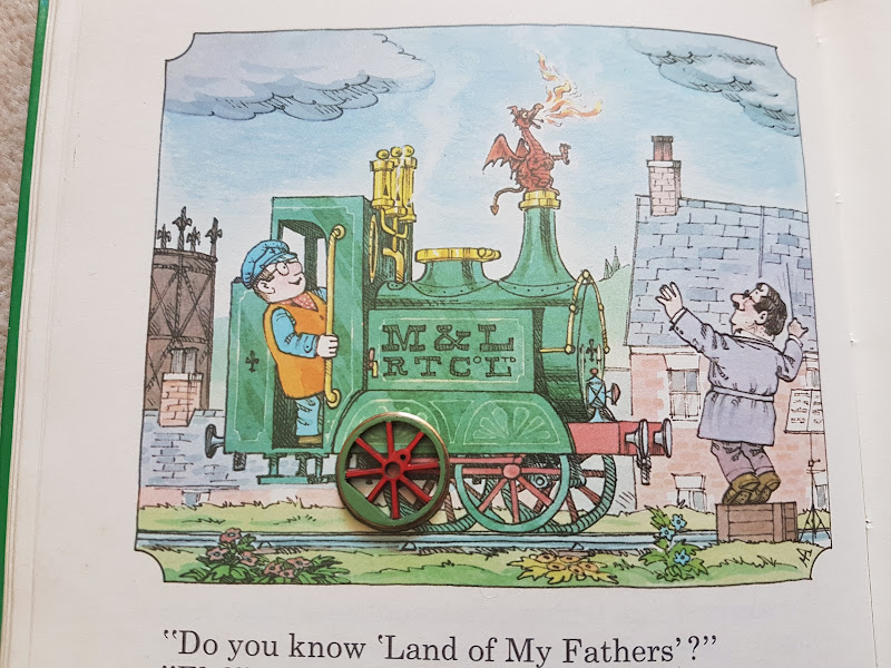 Now I just need to paint the other three wheels.
My first attempt involved painting on black primer, then the green for the rim, and then painting the spokes red. This worked but I found the very stark transition between the paint and the brass wheel tread was very obvious. What I've ended up doing is cleaning the wheels thoroughly, and then using Birchwood Casey Brass Black to darken the face of the wheel. The tread was then polished to remove any that had run down the side, before again applying paint, primer, and matt vanish; all by hand with a brush.
So far I've fully done one wheel. I'm sure the result could be better, painting between the spokes is a pain, but I'm happy with how it looks. More importantly I think it matches up with the pictures in my book pretty well.

Thursday, August 4, 2022
Colour Matching
With the curved handrail made up, I can think about moving on to painting Ivor. There is still work to do to the body (filling some gaps etc.) before it can be painted but I want to get the chassis painted and fully assembled, including pickups and coupling rods, first. Whilst I can easily paint the chassis black I also need to paint the wheels. These are always depicted as having red spokes and central boss, with a green balance weight (when it's drawn) and rim. The problem is what colour green should I use?
The instructions suggest that the model should be painted using "Plastikote 104S Enamel Paint Garden Green" but to my eye looking at this photo (lifted from the instruction sheet) that is way too bright a green. Given I'd like to use a paint I can use both with a brush and in the airbrush I had a look at the Vallejo Model Air colour chart I have (possibly a bit out of date now) to try and find a good match. The problem is that the colour of Ivor also seems to change from drawing to drawing in my childhood book and in the end I couldn't find a single colour that matched perfectly, although I did find four colours that seemed close to what I needed. A little bit of shopping later and I had four dropper bottles of paint. Of course paint in a bottle can be very misleading so I made up a quick test piece.
 I tried to replicate the final colour as close as possible (I settled on using a brush rather than the airbrush for speed) by giving the brass a black undercoat, then adding a patch of each colour, before sealing with a matt varnish. The numbers are part of the code of each paint so that I know which is which. My inital thought was that the one on the left (Model Air 71.006 Light Green Chromate) might be the best match. I know it's tricky giving varying lighting conditions and problems of the camera trying to correct etc. but does anyone want to have a guess before we go any futher?
Armed with the test piece the next step was to try it against some of the plates in my book. First stop, the front cover Now I've always thought that the front cover image is a bit dark, but my first thought of the paint on the left does look like a reasonable match, at least amongst the four paints on the test piece; the two on the right have way too much blue in them.
Next I had a look at the classic drawing of Ivor singing with the choir for the first time. As you can see the colours are much brighter than on the front cover, and now I think the second colour (Model Air 71.095 Pale Green) is a much better match, although not perfect.
I had a further flick through my book though and settled on this plate from the story where we first meet Idris Now to my eye that second colour is an almost perfect match to that plate, or at least as good as I'm likely to get without trying to mix my own custom colour. What does everyone else think?
The instructions suggest that the model should be painted using "Plastikote 104S Enamel Paint Garden Green" but to my eye looking at this photo (lifted from the instruction sheet) that is way too bright a green.


Armed with the test piece the next step was to try it against some of the plates in my book. First stop, the front cover

Next I had a look at the classic drawing of Ivor singing with the choir for the first time.

I had a further flick through my book though and settled on this plate from the story where we first meet Idris

Monday, July 25, 2022
A Curved Handrail
After the success of using a small jig to produce the straight handrails, I then attempted to do the curved rail for the front of the loco. I couldn't think of a clever way to design a jig for this one so had to do it freehand. Amazingly it turned out pretty well.
 I started with a straight piece of wire which I pulled round the handle of a small file (as you would when trying to curl ribbon when wrapping a present). This introduced a nice consistent curl to the wire, although one that wasn't quite as tight as I needed.I then slid on the five short handrail knobs. The middle one was soldered solid to the centre of the wire and was then gently fitted to the loco. This was then held in place with a piece of masking tape that ran along the top of the boiler over the knob and on to the smokebox front. I then fitted the other handrails into the holes and taped everything down. I could then solder these to the wire as well.
I then removed the handrail from the boiler and taped it flat to a piece of wood. The straight lengths which lead back to the side tanks were then soldered the best I could to the back of the handrail knobs. The extra wire was then trimmed away and the whole thing trial fitted back onto the model. Amazingly it all still fits (although yes it still needs cleaning up) and just about stays in place on it's own -- it's springing out slightly but nothing that won't be fixed once it's glued in place after the painting is done.

I then removed the handrail from the boiler and taped it flat to a piece of wood. The straight lengths which lead back to the side tanks were then soldered the best I could to the back of the handrail knobs. The extra wire was then trimmed away and the whole thing trial fitted back onto the model. Amazingly it all still fits (although yes it still needs cleaning up) and just about stays in place on it's own -- it's springing out slightly but nothing that won't be fixed once it's glued in place after the painting is done.
Friday, July 22, 2022
Handrail Jig
I hate making up handrails. It's not too bad if they are straight and attach to the locomotive via handrail knobs, but if you have to bend the wire at each end to fit into holes it's a complete nightmare. Previously I've done it by eye and ended up making a bunch before I get one that is just right. Some kits will proivide a jig (often just two correctly spaced cutouts on the edge of the fret of edged parts) to make life easier, but no such luck with this kit.
For Ivor I need to make up three rails. For now I'm ignoring the complex curved rail around the smokebox and am concentrating instead on the other two which are at the front of the cab to help Jones the Steam climb up into Ivor. Instead of struggling I thought I'd make up a quick jig so I could make two idenitcal rails, one for each side of the loco. I'm sure for many people reading this the idea won't be novel or exciting but I thought I might as well document it anyway.... if for no other reason so I remember the approach for next time!
First step was to stick a strip of masking tape down the side of the cab over both holes. I then used a 0.5mm drill bit to pierce two small holes inthe tape. The masking tape was then carefully transfered to a piece of thin plastic strip and the 0.5mm drill used to make two holes.
 I then removed the tape and cut a V shapped notch from the end of the stip down to one of the holes. This completes the jig showing just how easy it was to make.
 To make a handrail I started by putting a 90 degree bend into a short length of 0.5mm brass rod
 The short end of the bent rod was then pushed through the hole in the jig and flat nosed pliers were used to grip the other end, making sure to hold it tight just shy of the hole.
 The wire was then bent through the notch into the hole to give the second 90 degree bend against the pliers.
 The completed handrail can then be easily removed from the jig.
 And the most important bit, it fits perfectly into the holes on the locomotive.
 I still have to attach the handrails to the loco but that is usually trivial in comparison to making them up.
For Ivor I need to make up three rails. For now I'm ignoring the complex curved rail around the smokebox and am concentrating instead on the other two which are at the front of the cab to help Jones the Steam climb up into Ivor. Instead of struggling I thought I'd make up a quick jig so I could make two idenitcal rails, one for each side of the loco. I'm sure for many people reading this the idea won't be novel or exciting but I thought I might as well document it anyway.... if for no other reason so I remember the approach for next time!
First step was to stick a strip of masking tape down the side of the cab over both holes. I then used a 0.5mm drill bit to pierce two small holes inthe tape.


Wednesday, July 20, 2022
Two Small Steps for Ivor, One Giant Leap for Jones the Steam
Most of the remaining detailing of Ivor will involve me fabricating parts (like the hand rails) but there is one detail that needs making up from etched parts and these are the steps to help Jones the Steam up into the cab.
 The photo shows one assembled and one still as the flat part. Given their small size they were a nightmare to fold (even with the hold and fold) and in fact the close up photo shows I didn't quite get the right hand edge of that one completely square. I'll probably end up gluing these to the body as I won't be able to use the blow torch to attach them without them coming undone and I doubt I can get the heat in with the soldering iron, but at least the tricky part of making them up is done

Tuesday, July 19, 2022
Side Tanks and Boiler Fittings
With the cab and boiler fixed to the footplate the last piece of bodywork that needed fitting was the side tanks. These were simple to fold up and attach, again using the blow torch; still no burnt fingers and this time not only did I not undo any previous joints I also didn't set anything on fire. With the body essentially complete except for details like hand rails etc. I couldn't help but fit the chassis and rest the chimney and dome/water filler in place to finally get a feel for how the completed model will look.
 My first thoughts are that it looks prety good. The question is how well does it actually compare to the drawings in my childhood book that I'm using for prototype information.
 Well it's not terrible although there are a number of things that jump out at me as being not quite right. I think the body is too tall; specifically there is way too much boiler visible above the top of the side tanks, which in turn forces the cab to be too tall. The dome (not actually sure what it is as it seems to have a lid, but it isn't part of the tanks) is also too tall compared to the chimney. I might see if I can design and print a better proportioned replacement. Also I can't see guard irons by the wheels in any of the original drawings, so I wonder why they were added to the model chassis. Trying to work out if I should cut them off or leave them on.
I guess the issues are that the original drawings are obviously 2D, and so there is no requirement that the dimensions shown also work across the width of the loco; i.e. with a boiler that small the tanks would have to be much wider (across the loco) in order for them to touch the boiler and be that close to the edge of the footplate. Making the tanks wider would have looked really odd, so they increased the boiler size instead which then stretches the height of the cab etc. Basically the model was never going to be able to perfectly match the original drawings and I think the designer has done a reasonable job of making something that looks about right.
All in all, I'm happy with how it's turned out so far. Next step will be sorting out some of the detailing parts (hand rails, steps etc.) and then I can move on to painting. I'll start with painting the chassis and wheels so I can then deal with the coupling rods and correctly quartering the wheels, before I attempt to paint the body.
Monday, July 18, 2022
Fire in the Boiler
Having attached the boiler to the cab, the next step was to join that part to the footplate. After the previous issues with getting enough heat into the joints using a soldering iron, I didn't even bother trying and went straight to using the blow torch.
 Amazingly I managed to do all the joints without burning my fingers or having any of the previous joints come undone. I did manage to set fire to the piece of wood I was resting things on though which had the nice effect of smoke curling out of the hole where the chimney will fit!

Friday, July 15, 2022
We Need More Heat!
Whilst soldering the smokebox end of the boiler was reasonably straightforward, soldering the boiler to the cab was an absolute nightmare, although I did get there in the end and without any burnt fingers. Positioning the boiler was reasonably easy as there is a nice hole for the whistle that makes sure I know where the top is, and then it slots into a half etched ring on the cab front, and there are three little tabs on the end which further slot into holes on the cab front. The problem was that I just couldn't get enough heat into the joins to solder it in place.
 As you can see I did eventually get it soldered on but not without having to find a different source of heat. When I used the soldering iron the solder paste would run but not melt, and the solid solder would melt into a blob but I couldn't get it to flow. Both issues were caused because I couldn't get the solder hot enough as the heat is pulled away into the rest of the brass that makes up the cab and boiler rather than staying close to the tip of the soldering iron where I want it. The solution was to switch tools to something with a bit more heat.
 As you can see from the photo I own two gas torches. I've tried using the large cooks one before and managed to burn a whole through a brass part, so my plan was to use the small modellling torch instead. Unfortunately the small torch is useless. I had no problems filling it with gaz but couldn't get it to light properly. With the valve open the gaz was coming out and would light if I held a match in front of it, but it wouldn't stay lit when you removed the match. No idea what's wrong with it as although it's been in my toolbox for a while this was the first time I'd actually tried using it. So with more than a little trepedation I used the large cooks torch instead.
With the parts held gently in place, using a mixture of masking tape and coffee stirrers, I added some solder paste and then gently wafted the flame over the joint. Within no time at all the paste melted, flowed, and formed a nice joint. It's difficult to get the larger flame into odd places but I think I'll be using the torch again in the future for cases like this. Although I might see if I can find a smaller modelling torch that actually works.
Just as a final photo here is the mess I made on the inside of the boiler when trying to use the soldering iron. As you can see the solder turned into a blob but I just couldn't get it to flow and form a join. Anyway it was a useful lesson to learn that I can use the torch to make these kinds of joint if I need to. Still some cleaning up of the joint to do before I move on, but I think that is the hardest part of the body built quite successfully.


With the parts held gently in place, using a mixture of masking tape and coffee stirrers, I added some solder paste and then gently wafted the flame over the joint. Within no time at all the paste melted, flowed, and formed a nice joint. It's difficult to get the larger flame into odd places but I think I'll be using the torch again in the future for cases like this. Although I might see if I can find a smaller modelling torch that actually works.
Just as a final photo here is the mess I made on the inside of the boiler when trying to use the soldering iron. As you can see the solder turned into a blob but I just couldn't get it to flow and form a join. Anyway it was a useful lesson to learn that I can use the torch to make these kinds of joint if I need to.

Thursday, July 14, 2022
It's Still a Cylinder
Having rolled the boiler the next step is to fit the smokebox door (or what amounts to the smokebox door on Ivor). This is basically just a flat circular part that cabs one end of the boiler. It has a slight half etched rim around the edge to help positioning the two parts. I gently cut away the sacrificial pieces (needed to help during rolling) and then carefully taped the two parts together as best I could.
 Even having removed the sacrificial pieces there isn't a huge amount of space to get a soldering iron inside the boiler but I managed to avoid burning my fingers and am pretty happy with the result.
 In the cruel larger than life photo I can see a couple of tiny spots that might need a little filler, although I can't really see them with the naked eye. Either way, I'm really happy with that, given it's the first boiler I've rolled and assembled. Now I just have to solder it to the cab front hopefully straight so that the chimney will be properly vertical.


Wednesday, July 13, 2022
Mangled Brass or a Brass Mangle?
Those of you who have followed my modelling adventures for a while may remember that all the way back in 2014 I bought a Hold and Fold tool to make assembling etched kits easier. At the time I said it was nice and easy to use and in the years since it's become an indispensable tool. Also in that original post I mentioned not having a tool for rolling metal. Over the years since I've not found myself needing to do much rolling, mostly just needing a slight curve in cab roofs etc. For those parts I've made do with using a metal bar to gently introduce a curve. That works, but it's difficult to be precise. What I've not needed to do, until now, was to turn a flat sheet into a cylinder.
To date all the steam locomotive models I've built have used either a tube or a casting for the boiler, but for Ivor the boiler has to be rolled from a flat sheet to form a cylinder which then has a circle soldered on one end, while the other attaches to the cab. Given all the time and effort I've put into this build the last thing I want to do is completely mess up the boiler, and there is no way I could accurately roll that part using a simple bar so.... I've invested in a new tool.
 This is a set of 6" rolling bars from GW Models. I would normally point to a website when talking about a new tool, but they don't have a website, in fact I had to ring to check they had any in stock and then post a cheque to pay for them. Even before I tried using them I was impressed. They are just a lovely bit of engineering in their own right.
For anyone who doesn't know how they work, essentially the handle turns the two bottom rollers and thetop roller can be moved up and down. So you gently feed the metal through the gap and turning the handle moves it through. You then move the top roller down a little and repeat. Each time you move the top roller down it produces a tighter curve. I did about a quarter turn of the bolts each time so that I slowly increased the tightness of the curve until I had the right shape. Once happy you can undo the bolts and lift the top roller off which allows you to simply slide the part off the end. A quick check against the circle for the front of the boiler and everything looks good.
 Of course I still need to solder it all together so there is still plenty of time for me to mess it up!
Given how easy it was to roll the boiler you will be unsurprised to know that I think the rolling bars are fantastic and well worth the initial investment. Obviously it won't get as much use as the hold and fold (most kits will have tens of folds and possible only one part needing rolling) but it's one of those tools that does it's job so well and easily that it's worth having in your toolbox.
To date all the steam locomotive models I've built have used either a tube or a casting for the boiler, but for Ivor the boiler has to be rolled from a flat sheet to form a cylinder which then has a circle soldered on one end, while the other attaches to the cab.


For anyone who doesn't know how they work, essentially the handle turns the two bottom rollers and thetop roller can be moved up and down. So you gently feed the metal through the gap and turning the handle moves it through. You then move the top roller down a little and repeat. Each time you move the top roller down it produces a tighter curve. I did about a quarter turn of the bolts each time so that I slowly increased the tightness of the curve until I had the right shape.


Given how easy it was to roll the boiler you will be unsurprised to know that I think the rolling bars are fantastic and well worth the initial investment. Obviously it won't get as much use as the hold and fold (most kits will have tens of folds and possible only one part needing rolling) but it's one of those tools that does it's job so well and easily that it's worth having in your toolbox.
Monday, July 11, 2022
Welsh Tea
I mentioned in the previous post about the tap on the outside of the cab which is there for tea making purposes. While here is a terrible photo not only of the tap but also the teapot.
 As you can probably tell from the 1mm square grid these are tiny, but even so required some soldering; the tap is three layers and the teapot five. The cruel magnification shows there is still some cleanup to do as well.

Ivor's Cab
Although I seem to have done quite a bit of work on Ivor over the last month, amazingly I'd not actually used any new parts from the kit given that the wheels and gearbox were all made/bought separately. Building the cab, seems to have involved almost all the remaning etched parts though, so has been a bit of a mammoth session.
First up was building the back of the cab that also forms side of the coal bunker. This was nice and straightforward as it only involved soldering one detailed piece in place and making two simple folds. Annoyingly the door looks a little wonky in the photo but having stared at the part closely it seems level so not sure what is going on with the photo.
The rest of the cab is made from a single piece which needs folding and carefully soldering together. Prior to folding it up though, the backhead needs a lot of detail adding. There are no indications on the part itself as to where everything should go though, so I scaled one of the drawings from the instructions and stuck it to the etch. I then used a modelling knife to gently mark some of the lines and positions so I would know where everything should go. The paper was then removed, the glue cleaned off, and then the detail parts are put in place.

 Of course "the detail parts are put in place" hides quite a lot of work. Each of the gauges and controls have to first be made by laminating three layers of etch together before they can be soldered to the cab etch. After a lot of work with the soldering iron I gave up and used superglue to fit wire to represent the pipework. I've also not fitted all of the pipework shown in the instructions. Specifically it shows a pipe going horizontally to the edge on both sides of the cab; these are to feed the taps (for making tea) on the outside of the cab. I've been using the Ivor story collection book I've had since I was a child for prototype information and that only shows a tap on the right side of the cab, hence I've only fitted one pipe as I'll only be fitting one tap.

 With the backhead detailed the next step was to fold up the cab and incorporate the first piece I made up to build the coalbunker into the back of the cab. Including the coal bunker was nice and easy as there is an etched line it sits in. As the cab is all right angles the rest of it is prety easy to form as well. The only real problem is with the outiside of the coal bunker. This essentially folds across from one side and should nicely line up with a half etched seem on the other. Unfortunately it's slightly too wide. My guess is that when the artwork was drawn no allowance for material thickness was made, and so the part is too big by the thickness of the sheet. I filed it back a little and it's now mostly right, although looking at the finished can it's still ever so slightly wrong, but it's not visibly unless you are looking directly down on the model and I think once I've cleaned everything up (and yes I took the photos before cleaning up the excess solder) and put coal in the bunker it won't be noticable.
I know I'm not the most skilled person with a soldering iron (possibly as the soldering iron is cheap and fairly rubbish) but I'm pretty happy with how that all turned out... it's going to be a nightmare to paint the backhead detail but that's a problem for another day.
First up was building the back of the cab that also forms side of the coal bunker. This was nice and straightforward as it only involved soldering one detailed piece in place and making two simple folds.

The rest of the cab is made from a single piece which needs folding and carefully soldering together.


I know I'm not the most skilled person with a soldering iron (possibly as the soldering iron is cheap and fairly rubbish) but I'm pretty happy with how that all turned out... it's going to be a nightmare to paint the backhead detail but that's a problem for another day.
Subscribe to:
Posts (Atom)