It's been six and a half years since I was first given the PH Designs kit to build Ivor the Engine and while the build process hasn't taken that entire period it has been long and involved. There have been a number of frustrating setbacks but I'm so glad I stuck with the kit as I'm over the moon with the finsihed model. Hopefully my enthusiasm comes through in this video looking at the finsihed model...
Showing posts with label Ivor the Engine. Show all posts
Showing posts with label Ivor the Engine. Show all posts
Wednesday, July 19, 2023

Monday, July 3, 2023
Lining Ivor
After all the fun with the large 16mm scale Hudson Hunslet I've switched back to doing some work on Ivor.
 Since we last saw the model I've added the chimney and water filler cap and painted in their brass sections along with the brass window surrounds. Having added those I sprayed the model with a gloss varnish (specifically Vallejo Mecha Varnish 26.701) using the airbrush. While I don't want the model to have a gloss finish this was so that I could have a nice shiny surface to paint on the lining.
Doing the lining has been the most difficult part of the painting so far. The lines are etched into the model and I was hoping I could just flood the lines with yellow paint. Unfortunately that didn't seem to work, mostly as the yellow paint was almost transparent and so didn't show up. In the end I mixed yellow and ivory paint together to give a thicker more opaque paint. This was then painted, fairly roughly, over the lines with the excess then wiped away using a wet cotton bud. I did have to do some of the lines a couple of times to get enough paint into the lines; mostly as some of the lines were quite shallow due to a build up of the green paint.
Looking at the model I'm really happy with how the lining has turned out. Clearly it wouldn't be appropriate for most locos, but for Ivor I think it's perfect, as the colour in the originals varies in both hue and intensity along the lines and between different shots and I think I've managed to capture that quite well.

Doing the lining has been the most difficult part of the painting so far. The lines are etched into the model and I was hoping I could just flood the lines with yellow paint. Unfortunately that didn't seem to work, mostly as the yellow paint was almost transparent and so didn't show up. In the end I mixed yellow and ivory paint together to give a thicker more opaque paint. This was then painted, fairly roughly, over the lines with the excess then wiped away using a wet cotton bud. I did have to do some of the lines a couple of times to get enough paint into the lines; mostly as some of the lines were quite shallow due to a build up of the green paint.
Looking at the model I'm really happy with how the lining has turned out. Clearly it wouldn't be appropriate for most locos, but for Ivor I think it's perfect, as the colour in the originals varies in both hue and intensity along the lines and between different shots and I think I've managed to capture that quite well.
Thursday, April 27, 2023
Ivor's Buffer Beams: So Many Options
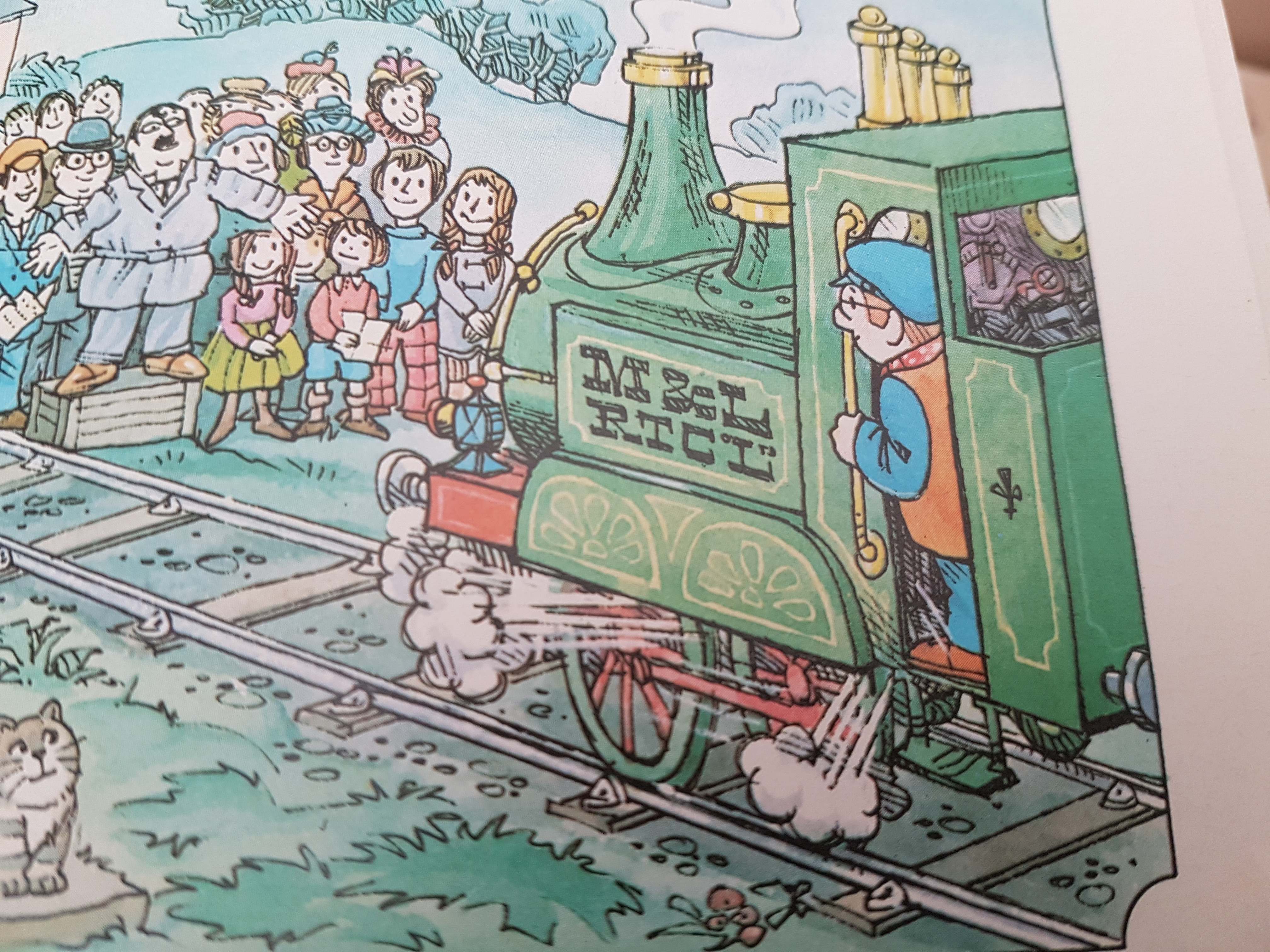
Having, put a base coat of green on Ivor I started looking thinking about painting the buffer beams. A quick glance at my standard reference work for this project, my childhood story book, and it quickly became clear that I had some decisions to make. The problem is that Ivor's buffer beams aren't coloured consistently throughout the book. From a thorough flick through it looks as if there are two options for the front and two for the rear.


 If we look across those three photos then you can see that.... for the rear buffer beam it's either red (as you might expect) or painted green the same as the body. For the front, you can see that while the front and sides are always red, the top surface is sometimes left green. Looking more closely I think the more common options, across the whole book, are for the front to be all red but the rear left green so that's what I've gone with.
 Of course it's also the easiest option as it meant I didn't have to try and get a perfectly horizontal masking line on the rear of the loco as there is no line in the etch between the back of the coal bunker and the buffer beam.



Wednesday, April 19, 2023
Back to the Top Left Hand Corner
With a little bit of sunshine appearing this afternoon I grabbed a few moments with the airbrush and.....
 Yes, Ivor is now green. It seems like an age since I last did anything with this model so it's nice to see the base coat on, especially as I'm happy with the colour now I can see it on the model. Phew!
I think the next step will be to mask up and paint the buffer beams and then maybe some of the detail paint work (like the rims around the windows). I'm in two minds about the exact ordering, as at some point I'm going to need to add some gloss varnish to some sections so that I can do the transfers and the lining, but I think that will be probably the last step before the final varnish coat and a light weathering..... unless anyone has a better suggestion for the order to do things?

I think the next step will be to mask up and paint the buffer beams and then maybe some of the detail paint work (like the rims around the windows). I'm in two minds about the exact ordering, as at some point I'm going to need to add some gloss varnish to some sections so that I can do the transfers and the lining, but I think that will be probably the last step before the final varnish coat and a light weathering..... unless anyone has a better suggestion for the order to do things?
Wednesday, August 24, 2022
Tidy Wiring
So the very last task to finish off the chassis was to tidy up the wiring. Because of the way the motor slides into the body I had to be careful to keep the wires running close to the gearbox and motor side, which was achieved with a bit of masking tape, and then it was just a simple case of shortening the wires and soldering them to the motor to give this...
 Of course with the wiring done and the chassis finished the obvious thing to do was to check that it still fitted into the body, and that the body didn't cause a short or rub anywhere that would cause an issue.
And to that the only thing I need to say is "sheer tea cufff, sheer tea cuff" (goodness knows how best to spell that but feel free to leave suggestions in the comments).

And to that the only thing I need to say is "sheer tea cufff, sheer tea cuff" (goodness knows how best to spell that but feel free to leave suggestions in the comments).
Tuesday, August 23, 2022
(Hopefully) Smoother Motion
As I mentioned in the previous post I think the poor running in one direction was down to the gearbox being able to rock on the axle when travelling one way but not the other. In an attempt to fix that I've bent the retaining clip slightly and added a small bit of masking tape as a shim to try and reduce the rocking as far as I can.
It's still not perfect but I think that's quite a bit better than before. The eagle eyes amongst you may spot that I've also painted the wheel centres and coupling rod retaining nuts red to match the drawings in my book. Just the wiring left to tidy up now.
It's still not perfect but I think that's quite a bit better than before. The eagle eyes amongst you may spot that I've also painted the wheel centres and coupling rod retaining nuts red to match the drawings in my book. Just the wiring left to tidy up now.
Monday, August 22, 2022
Coupling Rods: Now with Nuts
In my previous post, having quartered the wheels I tested the chassis with the coupling rods just slipped over the pins. The next step was to add the retaining nuts that will keep the rods from falling off to then cut the pins to length.
Before fixing the rods in place I double checked both rods, removing some slight burrs from the washers that keep them from rubbing the face of the wheels, and opened out the holes in the rods slightly. With the nuts just resting in place this seemed to work nicely so I took the plunge and carefully applied some Loctite 243 to fix the nuts in place. The excess crank pin was then carefully cut away with a jewellers saw.
After a little panic where it wouldn't move at all (one of the wires had come loose from the motor; they aren't soldered on yet) I was more than relieved to see it still working nicely. You may notice it moves smoother left to right than it does right to left. After watching it closely this seems to be becuase the gearbox can rock slightly on the axle when moving right to left as the retaining bracket I fitted doesn't hold it as tight as the chassis does when going the other way. I think that should be easy enough to tweak though.
So next steps are to fix the gearbox retaining bracket, clean up and paint the coupling rod retaining nuts, and then tidy up the wiring. After all that the chassis will be finished!
Before fixing the rods in place I double checked both rods, removing some slight burrs from the washers that keep them from rubbing the face of the wheels, and opened out the holes in the rods slightly. With the nuts just resting in place this seemed to work nicely so I took the plunge and carefully applied some Loctite 243 to fix the nuts in place. The excess crank pin was then carefully cut away with a jewellers saw.
After a little panic where it wouldn't move at all (one of the wires had come loose from the motor; they aren't soldered on yet) I was more than relieved to see it still working nicely. You may notice it moves smoother left to right than it does right to left. After watching it closely this seems to be becuase the gearbox can rock slightly on the axle when moving right to left as the retaining bracket I fitted doesn't hold it as tight as the chassis does when going the other way. I think that should be easy enough to tweak though.
So next steps are to fix the gearbox retaining bracket, clean up and paint the coupling rod retaining nuts, and then tidy up the wiring. After all that the chassis will be finished!
Friday, August 12, 2022
Joined Up Motion
So having got the pickups working nicely I turned my attention to quartering the wheels and trying the coupling rods. Unfortunately it was at this point that I started to panic.
You may remember from the previous post that I said the live wheels where a little loose on the axles and my plan was to fix these in place using Loctite 243. The reason I started to panic was because I suddenly realised that I had no idea if the Loctite would act as an insulator. If the wheels were insulated from the axle that would be a pain and I'd need to add pickups to the other side, and there isn't much space to do that.
Having used the Loctite to fix the crank pins in place I used my multimeter to check and my worst fears were confirmed; no continuity between the crank pin and the tread of the wheel. After a little bit of head scratching I realised I had a way out.
If you remember, the axles I turned are stepped which makes it easy to set the gauge. It also means that there is contact between the wheel and axle not just within the hole in the wheel but the shoulder on the axle pushes against the back of the wheel. My hope was that if I added the Loctite to the hole from the front of the wheel and then pushed the axle in from the rear it would ensure that there was a nice contact at the back of the wheel. Of course only one way to find out.
Fortunately it all worked nicely. Quartering the wheels was nice and easy (in comparison to every other kit I've built) because I could line up the spokes with the balance weights offset by 90 degrees. In the video the coupling rod is just slotted on, along with some washers to space it from the wheels, so hopefully it works as well once I put on the retaining nuts and trim down the crank pins.
You may remember from the previous post that I said the live wheels where a little loose on the axles and my plan was to fix these in place using Loctite 243. The reason I started to panic was because I suddenly realised that I had no idea if the Loctite would act as an insulator. If the wheels were insulated from the axle that would be a pain and I'd need to add pickups to the other side, and there isn't much space to do that.
Having used the Loctite to fix the crank pins in place I used my multimeter to check and my worst fears were confirmed; no continuity between the crank pin and the tread of the wheel. After a little bit of head scratching I realised I had a way out.
If you remember, the axles I turned are stepped which makes it easy to set the gauge. It also means that there is contact between the wheel and axle not just within the hole in the wheel but the shoulder on the axle pushes against the back of the wheel. My hope was that if I added the Loctite to the hole from the front of the wheel and then pushed the axle in from the rear it would ensure that there was a nice contact at the back of the wheel. Of course only one way to find out.
Fortunately it all worked nicely. Quartering the wheels was nice and easy (in comparison to every other kit I've built) because I could line up the spokes with the balance weights offset by 90 degrees. In the video the coupling rod is just slotted on, along with some washers to space it from the wheels, so hopefully it works as well once I put on the retaining nuts and trim down the crank pins.
Plunger Pickups
I may have mentioned before that I really really hate fitting pickups to locomotives. It doesn't matter how well built the model is, if it can't reliably pick up poer than it's next to useless. Unfortunately I find making and fitting pickups really difficult. Sometimes it's a problem with the material either causing too much friction (a problem I had with the 24hp Hudson Hunslet prototypes) or that they aren't springy enough and end up loosing touch with the wheels.
When desiging the wheels for Ivor I made the decision to isolate one wheel from the axle, leaving the other live. This means that for one side I can pick up power from the chassis (i.e. it goes through the wheel into the axle, and then through the bearings into the chassis) leaving me with only two wheels that need pickups.
In the past the pickups I've fitted have all been of a similar design, using wire to rub on the rear or flange of a wheel. For Ivor though the kit was designed to use plunger pickups which I'd never even seen before let alone used. I bought a pack of 10 from Alan Gibson, and it's a good job that was more than I needed.
Essentially each pickup consisted of three parts. There is a small plastic insert which fits into a 2.5mm diameter hole in the chassis in line with the back of the wheel. You then fit a tiny spring to a small turned brass plunger and slide that into the plastic housing. With the body of the plunger just inside the housing you bend the thin end over. This means the plunger now can't leave the plastic insert and is springy. A wire can then be soldered to the bent end to provide the electrical connection. Not sure how good that description was, but hopefully you get the general idea from this photo of them fitted to Ivor's chassis. Note the red wire soldered direct to the chassis to pick up power from the other side; I was originally going toput this underneath the chassis but it was a paint to get the iron in, hence scratching off some paint to solder it on the top.
With the pickups fitted I reassembled the chassis and temporarily wired the pickups to the motor for a test. Initially it was terrible. I think this was partly a lack of weight, but also I'd painted the rear of the balance weights and I think I'd strayed too far towards the edge of the wheels causing the pickups to loose contact with the metal surface. After removing a little of the paint (which you'd never see anyway) and adding blutak for weight we had this.
Clearly not perfect, but not terrible either. Hopefully once the wheels are quartered (the live wheels are slightly loose on the axle) and the coupling rod fitted to drive the second axles things should be a lot better, but given the struggle to get to this point I'm happy with that.
When desiging the wheels for Ivor I made the decision to isolate one wheel from the axle, leaving the other live. This means that for one side I can pick up power from the chassis (i.e. it goes through the wheel into the axle, and then through the bearings into the chassis) leaving me with only two wheels that need pickups.
In the past the pickups I've fitted have all been of a similar design, using wire to rub on the rear or flange of a wheel. For Ivor though the kit was designed to use plunger pickups which I'd never even seen before let alone used. I bought a pack of 10 from Alan Gibson, and it's a good job that was more than I needed.
Essentially each pickup consisted of three parts. There is a small plastic insert which fits into a 2.5mm diameter hole in the chassis in line with the back of the wheel. You then fit a tiny spring to a small turned brass plunger and slide that into the plastic housing. With the body of the plunger just inside the housing you bend the thin end over. This means the plunger now can't leave the plastic insert and is springy. A wire can then be soldered to the bent end to provide the electrical connection.

With the pickups fitted I reassembled the chassis and temporarily wired the pickups to the motor for a test. Initially it was terrible. I think this was partly a lack of weight, but also I'd painted the rear of the balance weights and I think I'd strayed too far towards the edge of the wheels causing the pickups to loose contact with the metal surface. After removing a little of the paint (which you'd never see anyway) and adding blutak for weight we had this.
Clearly not perfect, but not terrible either. Hopefully once the wheels are quartered (the live wheels are slightly loose on the axle) and the coupling rod fitted to drive the second axles things should be a lot better, but given the struggle to get to this point I'm happy with that.
Thursday, August 11, 2022
Crank Pins
Before I can start reassembling the chassis I need to complete the wheels by fitting the crank pins. These are simply 14BA bolts slotted through the hole in the wheel.
 I'd already prepared the holes (making sure they were wide enough and countersinking the hole so that the face of the screw head was flush with the rear of the wheel) so it was just a case of adding some Loctite 243 into the hole and then pushing the screws through and into place.
The pins are obviously way too long but I'll only cut them down once I've quartered the wheels and added the coupling rods, because if I cut them now it makes adding the retaining nuts more difficult.

The pins are obviously way too long but I'll only cut them down once I've quartered the wheels and added the coupling rods, because if I cut them now it makes adding the retaining nuts more difficult.
Wednesday, August 10, 2022
A Painted Chassis
Not much progress to report really, but I've moved on from having a single painted wheel to having all the parts for the chassis painted and ready to re-assemble.
 The next job will be to fit the crank pins to the wheels, and then I'll need to think about the pickups as I re-assemble the axles and gearbox. Once I have a chassis that picks up it's power from track I can then look at quartering the wheels and fitting the connecting rods. In other words there is still lots to do before I move on to painting the body. No idea how fast I'll get through all that but I'll be sure to post again as soon as there is more progress to report.

Friday, August 5, 2022
A Painted Wheel
In parallel to trying to determine the right colour of green paint to use, I've also been experimenting to try and find the best way of painting the wheels. Obviously I need to keep the paint off the flange and tread to ensure it can pick up power from the track. I initially thought about 3D printing some masks that would allow me to spray (at least the primer) onto the wheels and while they did work, I found they didn't give the best result around the edge of the wheel face. So I resorted to painting them by hand.
My first attempt involved painting on black primer, then the green for the rim, and then painting the spokes red. This worked but I found the very stark transition between the paint and the brass wheel tread was very obvious. What I've ended up doing is cleaning the wheels thoroughly, and then using Birchwood Casey Brass Black to darken the face of the wheel. The tread was then polished to remove any that had run down the side, before again applying paint, primer, and matt vanish; all by hand with a brush.
So far I've fully done one wheel. I'm sure the result could be better, painting between the spokes is a pain, but I'm happy with how it looks. More importantly I think it matches up with the pictures in my book pretty well.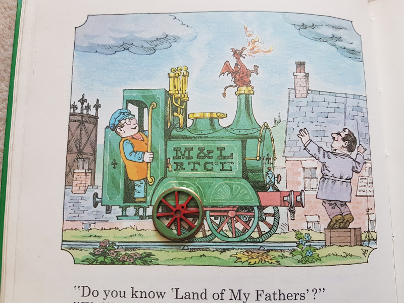 Now I just need to paint the other three wheels.
My first attempt involved painting on black primer, then the green for the rim, and then painting the spokes red. This worked but I found the very stark transition between the paint and the brass wheel tread was very obvious. What I've ended up doing is cleaning the wheels thoroughly, and then using Birchwood Casey Brass Black to darken the face of the wheel. The tread was then polished to remove any that had run down the side, before again applying paint, primer, and matt vanish; all by hand with a brush.
So far I've fully done one wheel. I'm sure the result could be better, painting between the spokes is a pain, but I'm happy with how it looks. More importantly I think it matches up with the pictures in my book pretty well.

Thursday, August 4, 2022
Colour Matching
With the curved handrail made up, I can think about moving on to painting Ivor. There is still work to do to the body (filling some gaps etc.) before it can be painted but I want to get the chassis painted and fully assembled, including pickups and coupling rods, first. Whilst I can easily paint the chassis black I also need to paint the wheels. These are always depicted as having red spokes and central boss, with a green balance weight (when it's drawn) and rim. The problem is what colour green should I use?
The instructions suggest that the model should be painted using "Plastikote 104S Enamel Paint Garden Green" but to my eye looking at this photo (lifted from the instruction sheet) that is way too bright a green. Given I'd like to use a paint I can use both with a brush and in the airbrush I had a look at the Vallejo Model Air colour chart I have (possibly a bit out of date now) to try and find a good match. The problem is that the colour of Ivor also seems to change from drawing to drawing in my childhood book and in the end I couldn't find a single colour that matched perfectly, although I did find four colours that seemed close to what I needed. A little bit of shopping later and I had four dropper bottles of paint. Of course paint in a bottle can be very misleading so I made up a quick test piece.
 I tried to replicate the final colour as close as possible (I settled on using a brush rather than the airbrush for speed) by giving the brass a black undercoat, then adding a patch of each colour, before sealing with a matt varnish. The numbers are part of the code of each paint so that I know which is which. My inital thought was that the one on the left (Model Air 71.006 Light Green Chromate) might be the best match. I know it's tricky giving varying lighting conditions and problems of the camera trying to correct etc. but does anyone want to have a guess before we go any futher?
Armed with the test piece the next step was to try it against some of the plates in my book. First stop, the front cover Now I've always thought that the front cover image is a bit dark, but my first thought of the paint on the left does look like a reasonable match, at least amongst the four paints on the test piece; the two on the right have way too much blue in them.
Next I had a look at the classic drawing of Ivor singing with the choir for the first time. As you can see the colours are much brighter than on the front cover, and now I think the second colour (Model Air 71.095 Pale Green) is a much better match, although not perfect.
I had a further flick through my book though and settled on this plate from the story where we first meet Idris Now to my eye that second colour is an almost perfect match to that plate, or at least as good as I'm likely to get without trying to mix my own custom colour. What does everyone else think?
The instructions suggest that the model should be painted using "Plastikote 104S Enamel Paint Garden Green" but to my eye looking at this photo (lifted from the instruction sheet) that is way too bright a green.


Armed with the test piece the next step was to try it against some of the plates in my book. First stop, the front cover

Next I had a look at the classic drawing of Ivor singing with the choir for the first time.

I had a further flick through my book though and settled on this plate from the story where we first meet Idris

Monday, July 25, 2022
A Curved Handrail
After the success of using a small jig to produce the straight handrails, I then attempted to do the curved rail for the front of the loco. I couldn't think of a clever way to design a jig for this one so had to do it freehand. Amazingly it turned out pretty well.
 I started with a straight piece of wire which I pulled round the handle of a small file (as you would when trying to curl ribbon when wrapping a present). This introduced a nice consistent curl to the wire, although one that wasn't quite as tight as I needed.I then slid on the five short handrail knobs. The middle one was soldered solid to the centre of the wire and was then gently fitted to the loco. This was then held in place with a piece of masking tape that ran along the top of the boiler over the knob and on to the smokebox front. I then fitted the other handrails into the holes and taped everything down. I could then solder these to the wire as well.
I then removed the handrail from the boiler and taped it flat to a piece of wood. The straight lengths which lead back to the side tanks were then soldered the best I could to the back of the handrail knobs. The extra wire was then trimmed away and the whole thing trial fitted back onto the model. Amazingly it all still fits (although yes it still needs cleaning up) and just about stays in place on it's own -- it's springing out slightly but nothing that won't be fixed once it's glued in place after the painting is done.

I then removed the handrail from the boiler and taped it flat to a piece of wood. The straight lengths which lead back to the side tanks were then soldered the best I could to the back of the handrail knobs. The extra wire was then trimmed away and the whole thing trial fitted back onto the model. Amazingly it all still fits (although yes it still needs cleaning up) and just about stays in place on it's own -- it's springing out slightly but nothing that won't be fixed once it's glued in place after the painting is done.
Friday, July 22, 2022
Handrail Jig
I hate making up handrails. It's not too bad if they are straight and attach to the locomotive via handrail knobs, but if you have to bend the wire at each end to fit into holes it's a complete nightmare. Previously I've done it by eye and ended up making a bunch before I get one that is just right. Some kits will proivide a jig (often just two correctly spaced cutouts on the edge of the fret of edged parts) to make life easier, but no such luck with this kit.
For Ivor I need to make up three rails. For now I'm ignoring the complex curved rail around the smokebox and am concentrating instead on the other two which are at the front of the cab to help Jones the Steam climb up into Ivor. Instead of struggling I thought I'd make up a quick jig so I could make two idenitcal rails, one for each side of the loco. I'm sure for many people reading this the idea won't be novel or exciting but I thought I might as well document it anyway.... if for no other reason so I remember the approach for next time!
First step was to stick a strip of masking tape down the side of the cab over both holes. I then used a 0.5mm drill bit to pierce two small holes inthe tape. The masking tape was then carefully transfered to a piece of thin plastic strip and the 0.5mm drill used to make two holes.
 I then removed the tape and cut a V shapped notch from the end of the stip down to one of the holes. This completes the jig showing just how easy it was to make.
 To make a handrail I started by putting a 90 degree bend into a short length of 0.5mm brass rod
 The short end of the bent rod was then pushed through the hole in the jig and flat nosed pliers were used to grip the other end, making sure to hold it tight just shy of the hole.
 The wire was then bent through the notch into the hole to give the second 90 degree bend against the pliers.
 The completed handrail can then be easily removed from the jig.
 And the most important bit, it fits perfectly into the holes on the locomotive.
 I still have to attach the handrails to the loco but that is usually trivial in comparison to making them up.
For Ivor I need to make up three rails. For now I'm ignoring the complex curved rail around the smokebox and am concentrating instead on the other two which are at the front of the cab to help Jones the Steam climb up into Ivor. Instead of struggling I thought I'd make up a quick jig so I could make two idenitcal rails, one for each side of the loco. I'm sure for many people reading this the idea won't be novel or exciting but I thought I might as well document it anyway.... if for no other reason so I remember the approach for next time!
First step was to stick a strip of masking tape down the side of the cab over both holes. I then used a 0.5mm drill bit to pierce two small holes inthe tape.


Wednesday, July 20, 2022
Two Small Steps for Ivor, One Giant Leap for Jones the Steam
Most of the remaining detailing of Ivor will involve me fabricating parts (like the hand rails) but there is one detail that needs making up from etched parts and these are the steps to help Jones the Steam up into the cab.
 The photo shows one assembled and one still as the flat part. Given their small size they were a nightmare to fold (even with the hold and fold) and in fact the close up photo shows I didn't quite get the right hand edge of that one completely square. I'll probably end up gluing these to the body as I won't be able to use the blow torch to attach them without them coming undone and I doubt I can get the heat in with the soldering iron, but at least the tricky part of making them up is done

Tuesday, July 19, 2022
Side Tanks and Boiler Fittings
With the cab and boiler fixed to the footplate the last piece of bodywork that needed fitting was the side tanks. These were simple to fold up and attach, again using the blow torch; still no burnt fingers and this time not only did I not undo any previous joints I also didn't set anything on fire. With the body essentially complete except for details like hand rails etc. I couldn't help but fit the chassis and rest the chimney and dome/water filler in place to finally get a feel for how the completed model will look.
 My first thoughts are that it looks prety good. The question is how well does it actually compare to the drawings in my childhood book that I'm using for prototype information.
 Well it's not terrible although there are a number of things that jump out at me as being not quite right. I think the body is too tall; specifically there is way too much boiler visible above the top of the side tanks, which in turn forces the cab to be too tall. The dome (not actually sure what it is as it seems to have a lid, but it isn't part of the tanks) is also too tall compared to the chimney. I might see if I can design and print a better proportioned replacement. Also I can't see guard irons by the wheels in any of the original drawings, so I wonder why they were added to the model chassis. Trying to work out if I should cut them off or leave them on.
I guess the issues are that the original drawings are obviously 2D, and so there is no requirement that the dimensions shown also work across the width of the loco; i.e. with a boiler that small the tanks would have to be much wider (across the loco) in order for them to touch the boiler and be that close to the edge of the footplate. Making the tanks wider would have looked really odd, so they increased the boiler size instead which then stretches the height of the cab etc. Basically the model was never going to be able to perfectly match the original drawings and I think the designer has done a reasonable job of making something that looks about right.
All in all, I'm happy with how it's turned out so far. Next step will be sorting out some of the detailing parts (hand rails, steps etc.) and then I can move on to painting. I'll start with painting the chassis and wheels so I can then deal with the coupling rods and correctly quartering the wheels, before I attempt to paint the body.


I guess the issues are that the original drawings are obviously 2D, and so there is no requirement that the dimensions shown also work across the width of the loco; i.e. with a boiler that small the tanks would have to be much wider (across the loco) in order for them to touch the boiler and be that close to the edge of the footplate. Making the tanks wider would have looked really odd, so they increased the boiler size instead which then stretches the height of the cab etc. Basically the model was never going to be able to perfectly match the original drawings and I think the designer has done a reasonable job of making something that looks about right.
All in all, I'm happy with how it's turned out so far. Next step will be sorting out some of the detailing parts (hand rails, steps etc.) and then I can move on to painting. I'll start with painting the chassis and wheels so I can then deal with the coupling rods and correctly quartering the wheels, before I attempt to paint the body.
Monday, July 18, 2022
Fire in the Boiler
Having attached the boiler to the cab, the next step was to join that part to the footplate. After the previous issues with getting enough heat into the joints using a soldering iron, I didn't even bother trying and went straight to using the blow torch.
 Amazingly I managed to do all the joints without burning my fingers or having any of the previous joints come undone. I did manage to set fire to the piece of wood I was resting things on though which had the nice effect of smoke curling out of the hole where the chimney will fit!

Friday, July 15, 2022
We Need More Heat!
Whilst soldering the smokebox end of the boiler was reasonably straightforward, soldering the boiler to the cab was an absolute nightmare, although I did get there in the end and without any burnt fingers. Positioning the boiler was reasonably easy as there is a nice hole for the whistle that makes sure I know where the top is, and then it slots into a half etched ring on the cab front, and there are three little tabs on the end which further slot into holes on the cab front. The problem was that I just couldn't get enough heat into the joins to solder it in place.
 As you can see I did eventually get it soldered on but not without having to find a different source of heat. When I used the soldering iron the solder paste would run but not melt, and the solid solder would melt into a blob but I couldn't get it to flow. Both issues were caused because I couldn't get the solder hot enough as the heat is pulled away into the rest of the brass that makes up the cab and boiler rather than staying close to the tip of the soldering iron where I want it. The solution was to switch tools to something with a bit more heat.
 As you can see from the photo I own two gas torches. I've tried using the large cooks one before and managed to burn a whole through a brass part, so my plan was to use the small modellling torch instead. Unfortunately the small torch is useless. I had no problems filling it with gaz but couldn't get it to light properly. With the valve open the gaz was coming out and would light if I held a match in front of it, but it wouldn't stay lit when you removed the match. No idea what's wrong with it as although it's been in my toolbox for a while this was the first time I'd actually tried using it. So with more than a little trepedation I used the large cooks torch instead.
With the parts held gently in place, using a mixture of masking tape and coffee stirrers, I added some solder paste and then gently wafted the flame over the joint. Within no time at all the paste melted, flowed, and formed a nice joint. It's difficult to get the larger flame into odd places but I think I'll be using the torch again in the future for cases like this. Although I might see if I can find a smaller modelling torch that actually works.
Just as a final photo here is the mess I made on the inside of the boiler when trying to use the soldering iron. As you can see the solder turned into a blob but I just couldn't get it to flow and form a join. Anyway it was a useful lesson to learn that I can use the torch to make these kinds of joint if I need to. Still some cleaning up of the joint to do before I move on, but I think that is the hardest part of the body built quite successfully.


With the parts held gently in place, using a mixture of masking tape and coffee stirrers, I added some solder paste and then gently wafted the flame over the joint. Within no time at all the paste melted, flowed, and formed a nice joint. It's difficult to get the larger flame into odd places but I think I'll be using the torch again in the future for cases like this. Although I might see if I can find a smaller modelling torch that actually works.
Just as a final photo here is the mess I made on the inside of the boiler when trying to use the soldering iron. As you can see the solder turned into a blob but I just couldn't get it to flow and form a join. Anyway it was a useful lesson to learn that I can use the torch to make these kinds of joint if I need to.

Thursday, July 14, 2022
It's Still a Cylinder
Having rolled the boiler the next step is to fit the smokebox door (or what amounts to the smokebox door on Ivor). This is basically just a flat circular part that cabs one end of the boiler. It has a slight half etched rim around the edge to help positioning the two parts. I gently cut away the sacrificial pieces (needed to help during rolling) and then carefully taped the two parts together as best I could.
 Even having removed the sacrificial pieces there isn't a huge amount of space to get a soldering iron inside the boiler but I managed to avoid burning my fingers and am pretty happy with the result.
 In the cruel larger than life photo I can see a couple of tiny spots that might need a little filler, although I can't really see them with the naked eye. Either way, I'm really happy with that, given it's the first boiler I've rolled and assembled. Now I just have to solder it to the cab front hopefully straight so that the chimney will be properly vertical.


Subscribe to:
Posts (Atom)